|
Page 1
Go To Page: 1
2
3
4
5
6
7
Back to
Baja Bug Update main page
Disassembly and IRS
Pivot Installation
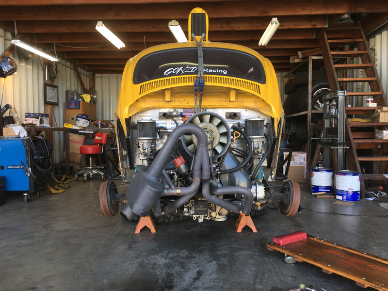
Type 4 engine and original "swing-axle"
transaxle
This chassis was built in 1968 - that makes it
a "swing-axle" rear suspension and you can see one of the negative
aspects in this photo: the camber of the rear wheels changes
significantly with suspension travel. Here you see lots of
"positive" camber with the suspension on the lower stops; there
would be "negative" camber while on the upper stops.....
Additionally, the total suspension travel is limited by the
"swing-axle" design so the "IRS" rear suspension is much preferred
in off-road use. Our suspension update will convert this car
to a rear suspension system identical to that on our 5/1600 car,
giving us as much as 16" of rear wheel suspension travel while
minimizing camber changes.
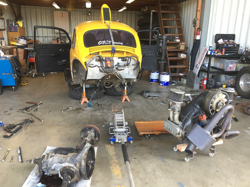
Step 1 - remove the engine and swing-axle
transaxle
With the engine and transaxle out of
the way, we can begin the conversion to IRS rear suspension.
While it's out of the car, Trevor plans to freshen up the engine and
install a new camshaft that will better match the intended purpose
of the car (a pre-runner).
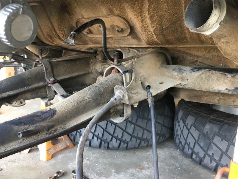
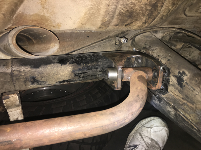
The swing-axle suspension beam and "frame
horns"
The frame horns must be modified to allow
installation of the inner IRS pivot brackets - they locate at the
intersection of the beam and frame horns and as you can see here,
there's a bunch of structure/stuff in the way..... Some of the
hardware in this photo is a "hard mount" kit for mounting of the old
transaxle - that'll all go in the scrap bin and we'll fabricate new
mounts to interface with the "mid-mounts" that'll be part of our
new "Bus" transaxle.
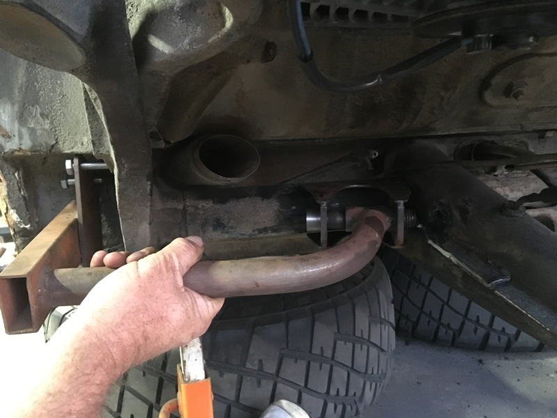
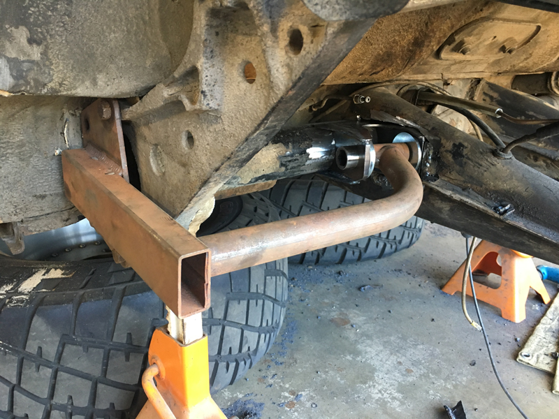
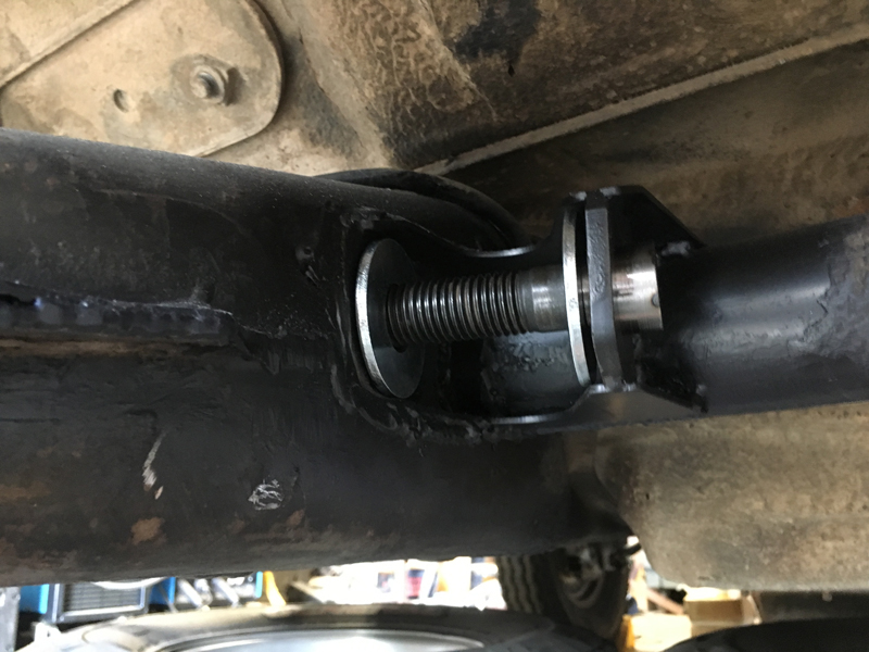
Beginning the process of fitting the IRS pivot
Here we're using a commercially supplied "jig"
to position the driver's side IRS pivot so that we can determine
where to clearance the frame horns. The pivot will be inset
into the horn so that the innermost rear edge of the pivot is
essentially flush with the frame horn, requiring that we cut a
fairly large hole in the horn for a portion of the pivot to reside
inside the horn. Ultimately, we want to fit the pivot bracket
so that the jig bolts flat to the torsion housing spring plate cap
location while the boss at the pivot end is centered in the pivot
bracket. We'll try to remove as little material as
possible but may end up needing to close some gaps - it's a trial and
error process when you do it as infrequently as we do......
Frame horn cut for the IRS pivot installation
Here you can see the frame horn opening with
the pivot close to its final position. These are heavy duty
"race" IRS pivots, same as on our 5/1600 car. We had the
brackets but had to fabricate special "shoulder" nuts to weld on to
the pivot faces that are inside the frame horns and we had to turn
down the bolt heads to act as the outer bearing surfaces - the bolt
head needs to fit snugly inside the hole in the outer plate of the
IRS bracket.
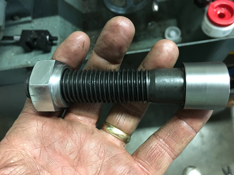
Custom Pivot Bolt and Nut
We modified the bolts and nuts from
commercially available stock - both the bolt heads and the nuts are
machined to act as bearing surfaces with the pivot brackets.
The pivots are heavy duty "race" parts and these pivot bolt
assemblies are much larger than stock. The nuts weld to the
pivot brackets on the face that is recessed inside the "frame
horns".
Pivot
bracket inset into frame horn
You can see that we ended up cutting the hole a
bit over-size so we had to make a "filler" plate to close the gaps.
The frame horn area just to the right of the rear edge of the
bracket is rough because that's where the stock parking brake cable
exits. We had to remove the cable support structure, leaving
the area a bit disturbed - we'll close up and smooth over the area
before moving on. Also, the frame horn "seam" has a flange
that intrudes into where the trailing arm will mount - we'll trim
that back as necessary and re-weld the seam. Surprisingly, a
fair amount of trimming of the actual pivot bracket was necessary to
achieve the correct positioning (we had to remove lots of material
to get them to sit tight to the beam where the jig wanted them).
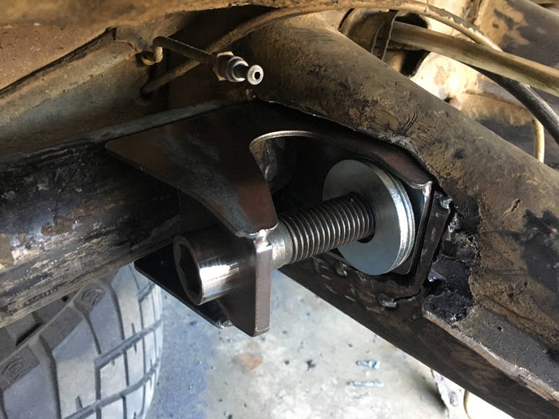
Final IRS pivot location, ready to be tacked in
place
Now that all the IRS bracket trimming is
complete, you can see that the jig bolts flat to the spring plate
cap mount (left side of the jig) and the jig boss is centered in the
bracket. Trevor tack welded the bracket in place, removed the
jig then fully welded the bracket. The passenger side IRS
pivot was installed in the same way. Next, we'll
grind the welds around the bracket to produce a smooth transition
then paint.
We're using spare 5/1600 parts for this
conversion - trailing arms, spring plates, torsion bars and axles -
all parts that have been raced multiple times, then retired to serve
as spares. One of the trailing arms was a bit "tweaked"; it
was damaged in our 2012 Baja 500 roll-over. We were able to
return it to serviceable condition without too much trouble and it
should do well in this pre-runner. Everything else seems to be
in good shape so we'll just clean it up, paint it and bolt it on -
the car will be back on the wheels in no time!
Passenger side IRS pivot final welded and ready
for the trailing arm.
We still need to install a small pivot bolt "locking" device to keep
the pivot bolt from rotating during service - the trailing arm would
otherwise be able to rotate the bolt as the suspension cycles
up/down and it could eventually "unscrew" all the way out and we'd
lose the wheel on that side.....
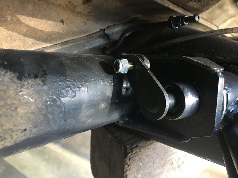
Driver's side Pivot pin "lock"
This lock secures the pivot pin so that it can't
rotate as the trailing arm articulates - it's just a bolt head
welded to a tab that engages the Allen head of the pivot bolt,
restraining it from rotating while the tab is secured with the small
bolt you see at the top.
Page 1
Go To Page: 1
2
3
4
5
6
7
Back to
Baja Bug Update main page
|