Race Prep. and Repairs
Overview and Checklist
Post Race Disassembly
Post Race Inspection
Repairs and Preventative Maintenance
CV Polishing and Prep.
Suspension Tuning
![]()
Repairs and Preventative Maintenance
|
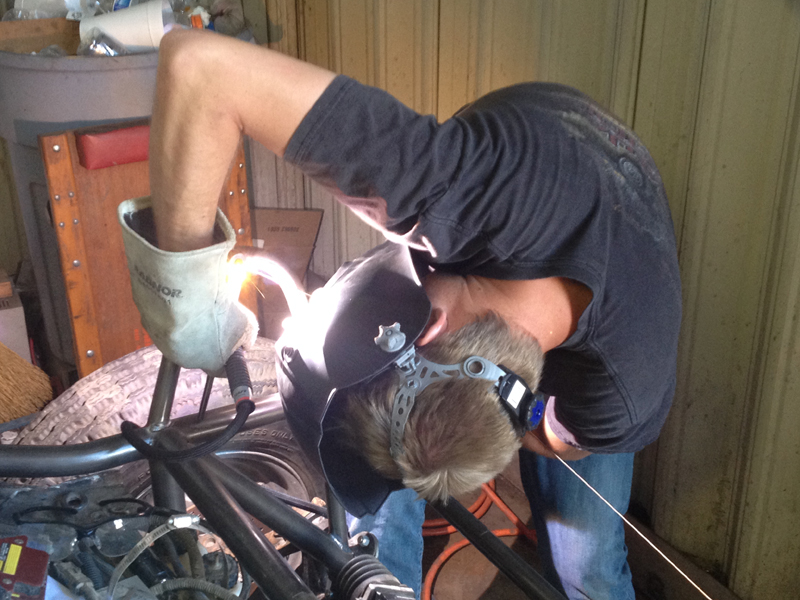
We are not out to take a leisurely trail ride through the desert; we run the car as hard and fast as it will go most of the time. As you might expect, we break things as a result; our "Race Prep." efforts are intended to identify all the problems that we encounter during each race so that we can avoid them during the next. After every race, we strip the car down to the last nut and bolt and inspect it carefully. We note the problems we need to address and discuss how best to proceed. Usually, the problems and solutions are obvious - but not always. I'll try to show a few examples of problems we've encountered and the how and why of the repairs.
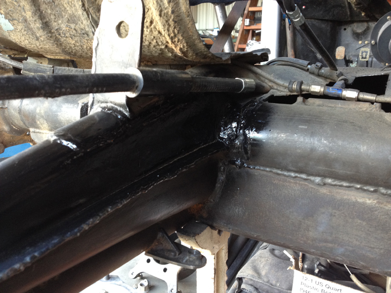
Broken Rear Torsion Housing
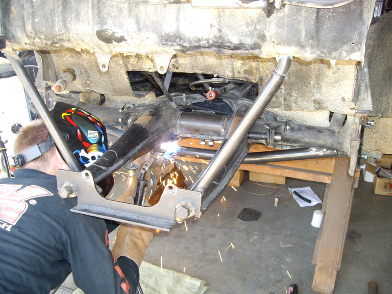
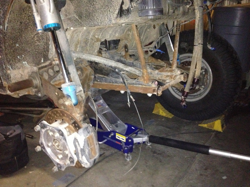
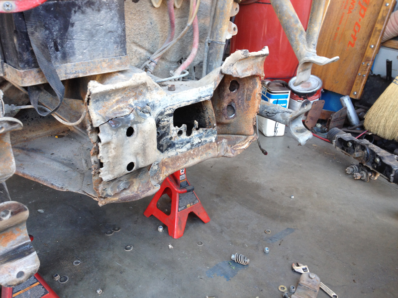
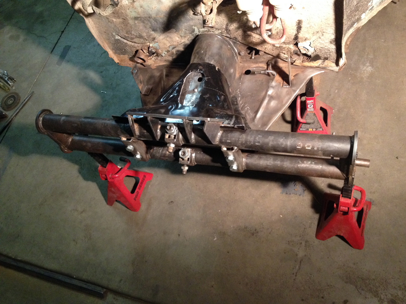
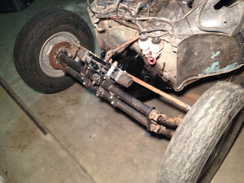
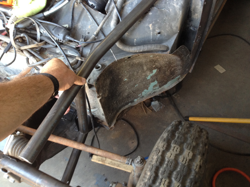
This was our first major problem with the car, discovered at the 2009 SCORE San Felipe 250. This is a larger problem than just some cracking that we can weld and forget about; these cracks are evidence of a broken rear torsion housing - a critical part of the car that we can't just slap a band aid on! Some VW "experts" consider this to be a fatal injury for a 5/1600 car; we didn't agree with that analysis and chose to repair and reinforce the torsion housing. Having decided on a course of action, we disassembled the car, put it on jack stands and began attempting to locate the exact position of the break. As we expected, it was hidden inside the "frame horn" so we had to cut a hole to gain access to the problem area first. Once we were able access the break, we carefully re-aligned the torsion housing and welded it back together. Following the initial repair, we added further support elements as allowed in the SCORE class 5/1600 rule set.
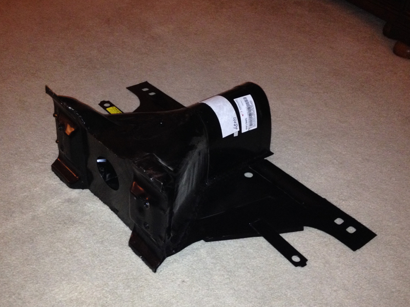
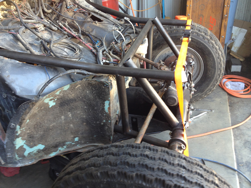
Adding this truss structure was the best option (in our opinions) to save the car once the torsion housing was broken. We could have welded in a "new" torsion housing but that would have entailed other problems for us..... The truss structure does add a bit of weight; it also reduces our ground clearance by about an inch. We believe that those are acceptable penalties for the benefits it offers.
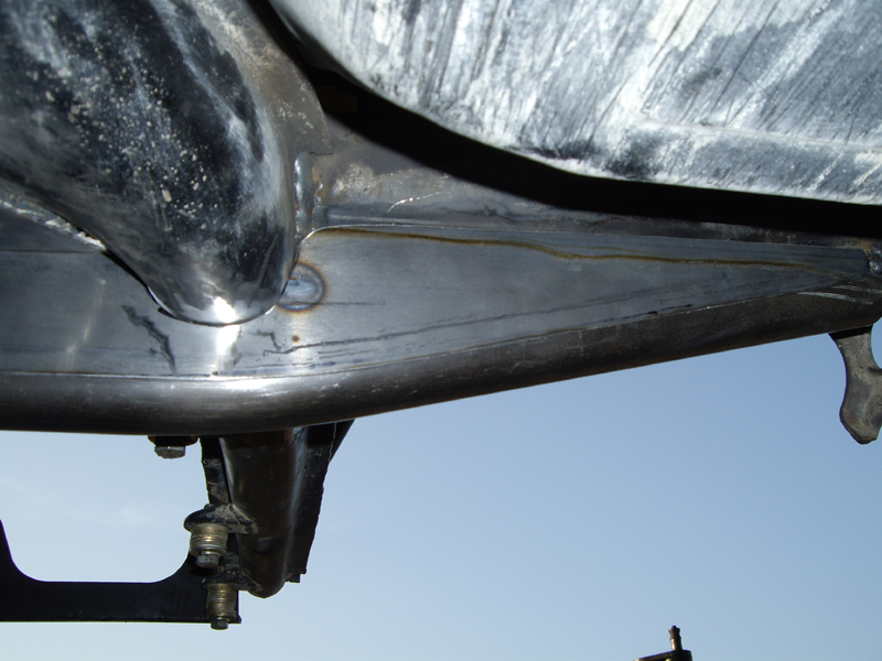
The shear webs (front and rear), once welded in place, tie the truss tube to the torsion housing across its full width, adding an immense amount of strength/stiffness to it.
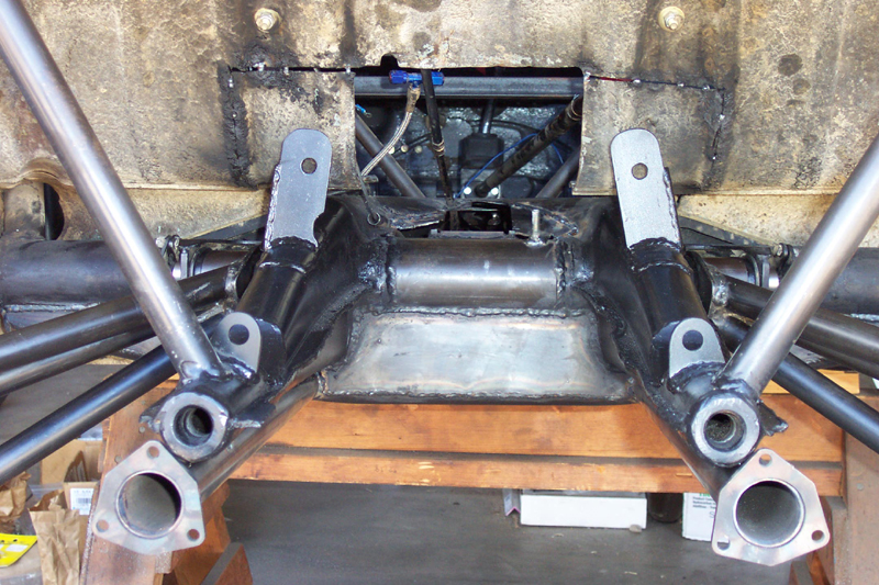
This was a significant problem that required us to come up with a lasting solution if we wanted to continue racing the car. It was a challenge, but the results speak for themselves; we've run two Baja 500's, two Baja 1000's (peninsula runs), several San Felipe 250's and the SoCal 250 without further issues! We still monitor the torsion housing carefully though......
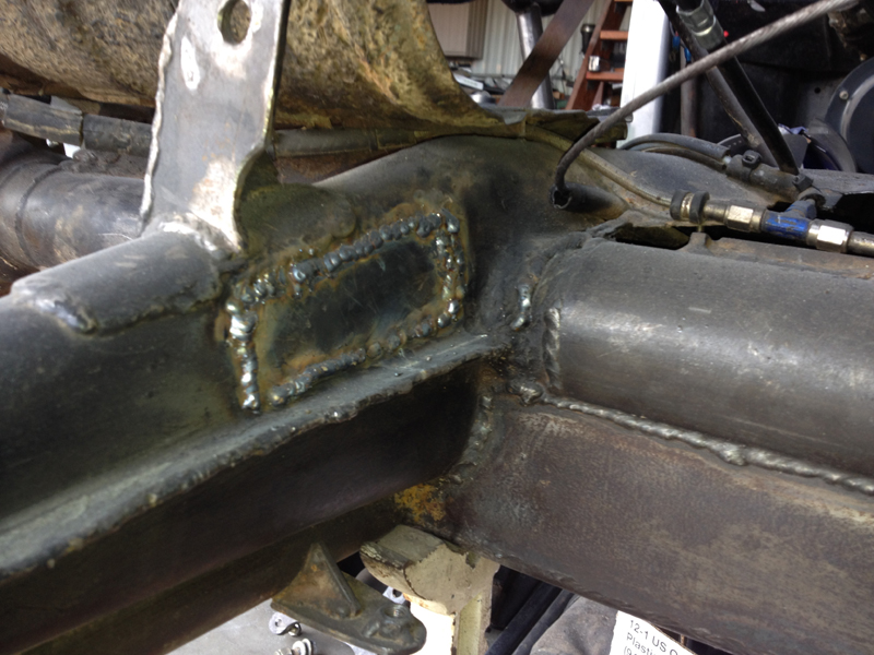
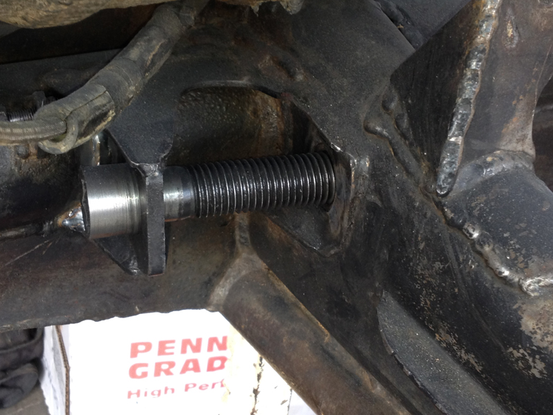
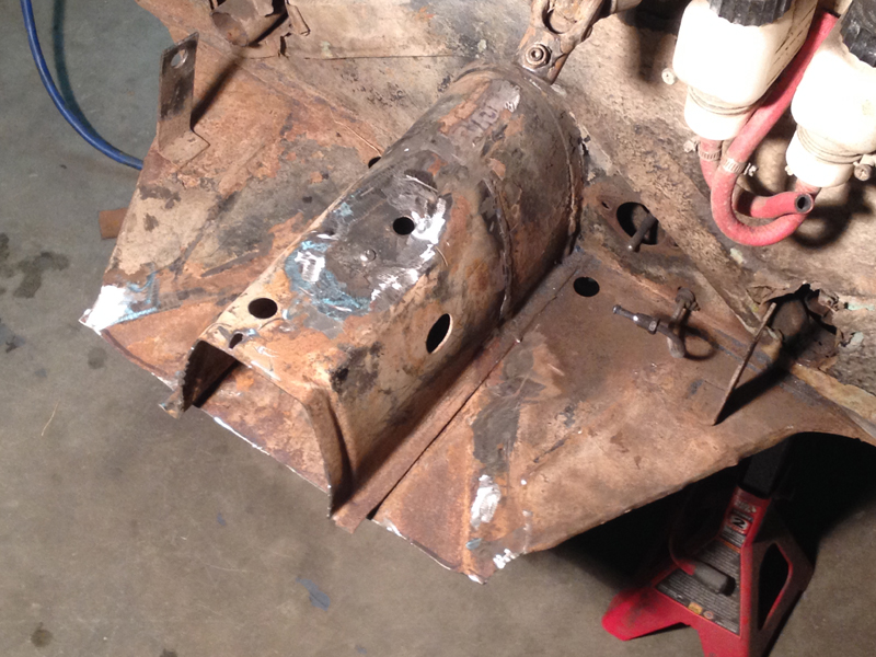
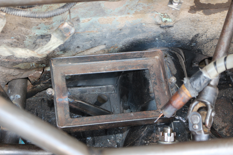
Failed Left IRS Pivot Bracket When disassembling the car following the 2014 SCORE San Felipe 250, we discovered that we couldn't get the left IRS pivot bolt out of the trailing arm/pivot bracket. We could turn the bolt but it wasn't coming out..... Obviously, the nut that engages that bolt had become detached from the pivot bracket allowing it to turn freely. Nothing's ever easy in racing it seems; that nut is welded (well, it's supposed to be anyway) to the portion of the pivot bracket that is encased inside the "frame horn" that cradles the transaxle/engine. Repairing the bracket required that we cut into the frame horn to gain access - I don't like cutting into structural elements but we had no choice here..... Once we had access, it was a simple matter of cleaning up the area, welding the nut back in place (making sure it was aligned correctly) and then replacing the portion of the frame horn we removed for access.
We were careful to use a very thin "cut-off" wheel when we cut the opening; we didn't want to have large gaps to fill when we replaced the material. The metal in this area isn't very thick so rather than welding in a continuous "bead", we used a series of "tacks" to secure the piece.
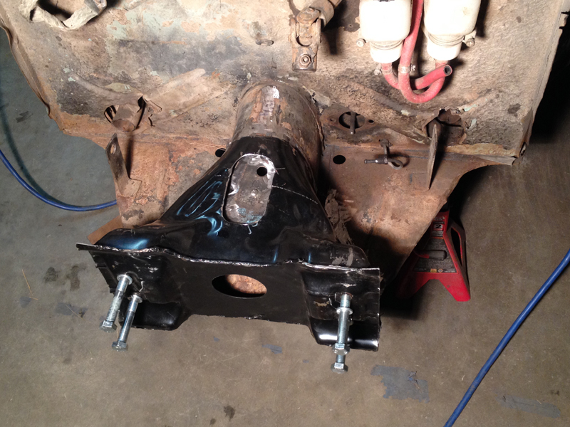
We didn't really need to spend the time to make the area look the way it did prior to the repair but we take some "pride in workmanship" with our car, something we don't see much of in desert racing..... Now that the area has been smoothed and painted, it's hard to tell that we did the repair at all.
The design of this pivot is such that if the nut (hidden inside the frame horn) detaches from the bracket, the pivot bolt becomes free to "float" and the loads transmitted from the trailing arm are borne entirely by the head of the bolt. As a result of this particular failure, the pivot bracket was showing some signs of distress (cracking). We could see no reason for the cracking until we discovered that we couldn't get the bolt out of the bracket.....
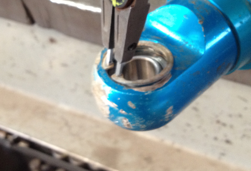
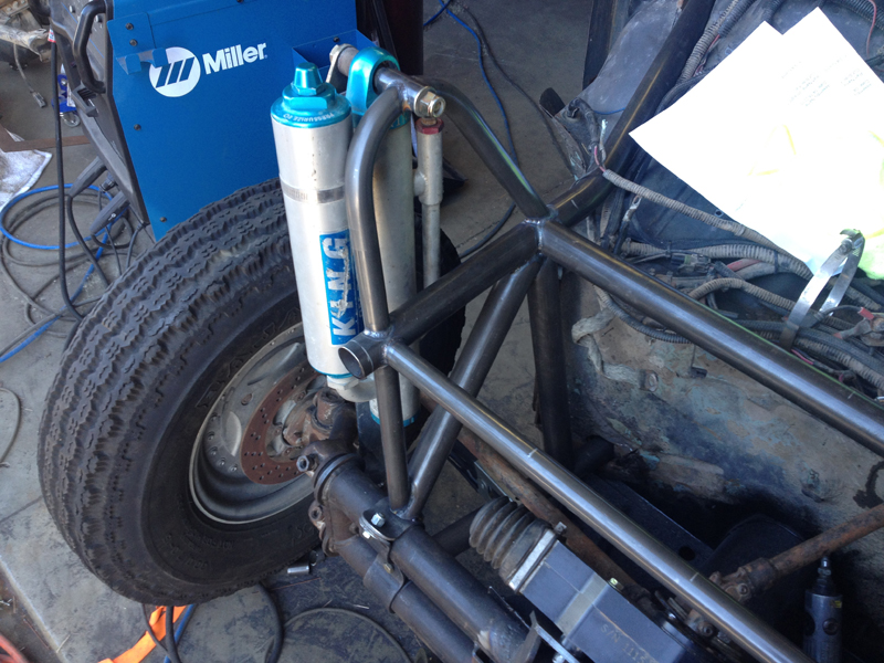
Shock End Bearing Preventative Maintenance Our shocks are attached to the car with bolts that go through "spherical bearings" secured within the top and bottom ends of each shock. These special bearings live a hard life; they are exposed to water, dust, impact and heat. We find that we can usually count on them for about 1500 to 2000 race miles before they need replacement. Typically, we replace them before they begin showing any signs of side-to-side "play" but we obviously want to get as much use out of them as possible. Most are connected to the car in a "double shear" type of mount but some are not. When they fail in a non-double-shear situation, they can allow the shock to become detached at that point - a really bad thing..... The "final solution" when not mounted in double shear is to use large diameter washers on the the bolts to keep the shock from coming free in the event of a bearing failure; our preferred option is to replace them before the "final solution" becomes necessary! That's why we replace them when they start getting "loose" and before they show any side to side play.
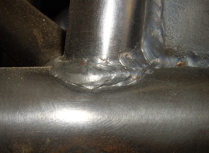
Chasing Cracks When building a car to race in the desert, one must make weight/strength compromises; a strong car is usually a heavy (slow) car, while a light car may be too fragile to finish a race. The problem during the design stage is to balance the two issues; we want a fast (light) car but we also need it to be strong enough to survive the race..... If we make it too light, it may suffer race ending structural failures frequently. If we make it too heavy, it may be too slow to be competitive. The ideal balance (in our opinion) is a car that's light, but not so light that it doesn't finish races. That implies that there may be problems with the structure following a race, but the car makes it to the finish line quickly. That's the goal we were trying to achieve when we designed/built our car; we think that's what we ultimately ended up with. Our car has finished every race it started (except the one where we crashed into an immovable object at 50 mph and tore the engine out of the car.....) and it's faster than the average 5/1600 car. We do have to repair some minor structural cracking after nearly every race, however.
This is one of our front shock mount "hoops". You might not be able to see it in this photo but there is a "hairline" crack along the bottom edge of this weld. The hoop takes a beating every race; thousands of "up-down" cycles of the shock before we get to the finish line. We watch these areas very closely for problems. Visible on the right side of the tube is a gusset we added after the original build to mitigate the on-going problems we were having in this area. We chose to grind the problem area and re-weld this time.
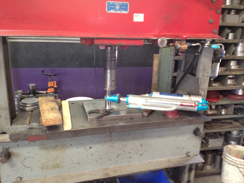
Front Torsion Adjuster Preventative Maintenance
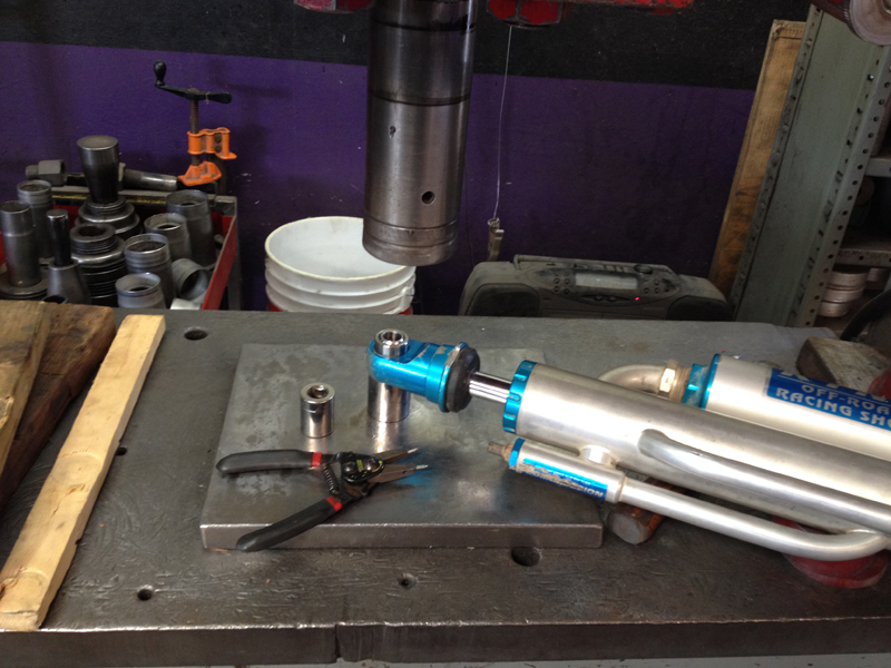
These two assemblies allow us to adjust the Torsion Pack "pre-load" on our front suspension. They are critical to the performance of our car so we are careful to inspect/overhaul them after every race. This is one of those lessons learned along the way; our upper adjuster failed during the 2010 Baja 1000, allowing our front suspension to "sag" much lower than we wanted. That forced us to slow down every time we came to rough terrain (all the time....), not ideal when you're racing.....
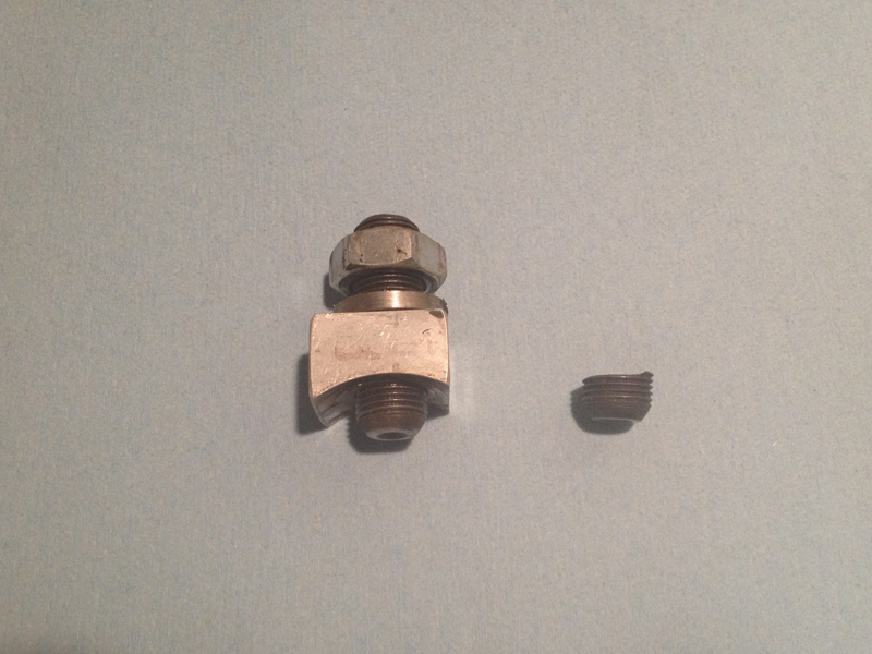
The assembly I'm holding is what actually rotates the torsion bars, setting the desired pre-load (ride height). The large set screw threads into in a cylinder (visible through the slotted hole in the upper tube) that holds the center of the torsion pack while a perpendicular adjuster screw pushes on the aluminum "slide", rotating the assembly as necessary. When you get to the desired setting, the large nut is tightened to secure the assembly in position. In actual practice, the large set screw in the assembly can end up failing due to the bending loads it's exposed to by the adjustment screw (even though it looks as if the aluminum slide was designed to eliminate or reduce that problem - notice that the set screw is "off-center" in the slide, biased towards the front so that the slide tends to counter the bending load the adjustment screw imparts). We replace that large bolt every race as a result. Another note - this type of set screw typically has a fairly sharp edged "cup" on the end that would damage the torsion plates if not removed; we grind and polish the area smooth before installation.
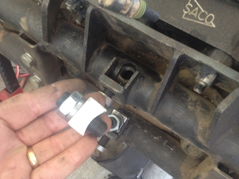
As you can see, the majority of the adjuster on the right is missing in action somewhere in Baja California Sur...... When you place such huge performance demands on suspension parts, things fail.... These are "heavy duty" parts and if we weren't racing, they'd last virtually forever. This particular adjuster screw failed about 1100 miles into a 1275 mile SCORE Baja 1000 "peninsula run", making life difficult for the remaining 175 miles and resulting in the complete failure of the front suspension and support structure by the finish line (and a DNF by 45 seconds!). We had spare parts in the chase truck but it didn't fail until after they were beyond our ability to get to them in a reasonable amount of time (Murphy's law).
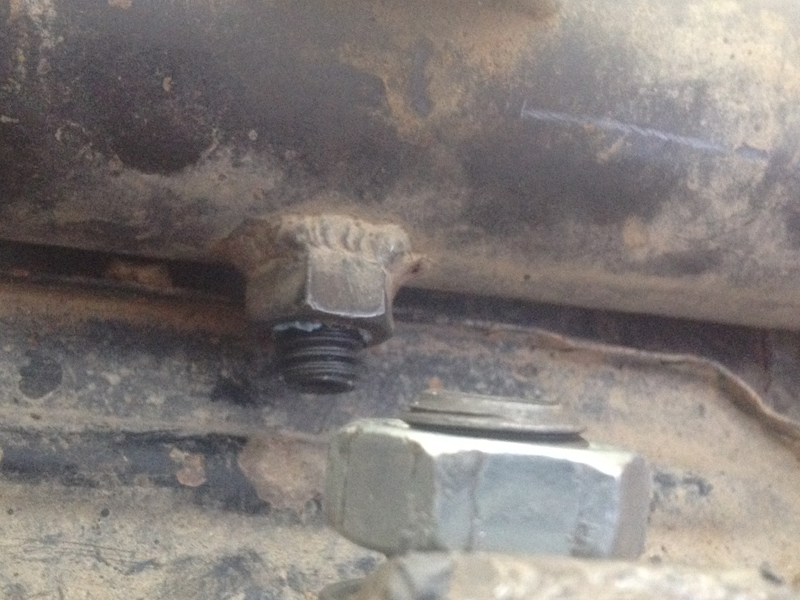
To help reduce the bending loads the main bolt is exposed to, we added these set screws to the bottoms of both beam tubes. This allows us to better restrain the adjuster cylinder once we've set the desired pre-load, reducing the bending loads on the main bolt.
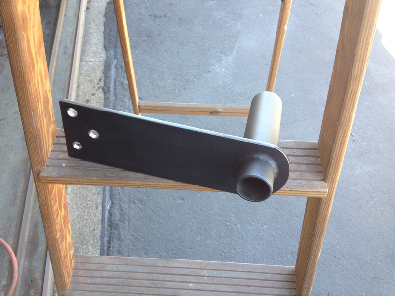
Fabricating New Spring Plates The spring plates on a "torsion bar" VW rear suspension system connect the trailing arms to the torsion bars. They carry all the rear suspension "spring load" to the rear wheels from the chassis; in addition to transmitting the spring loads, these plates see huge "twisting" forces as the suspension cycles up and down due to the design of the trailing arm attachments. They are a critical part whose failure could end our race (or at least cost us several hours)..... We inspect and repair them as necessary after every race; this time, the nature of the problems we saw seemed to indicate that they were near the end of their "race life". We could repair them but not sure how successfully...... Rather than run the risk of a failure during the Baja 1000 (our next scheduled race), we chose to replace them. Unfortunately, they are not "off the shelf" items; we have to custom fabricate them from something that is available off the shelf.
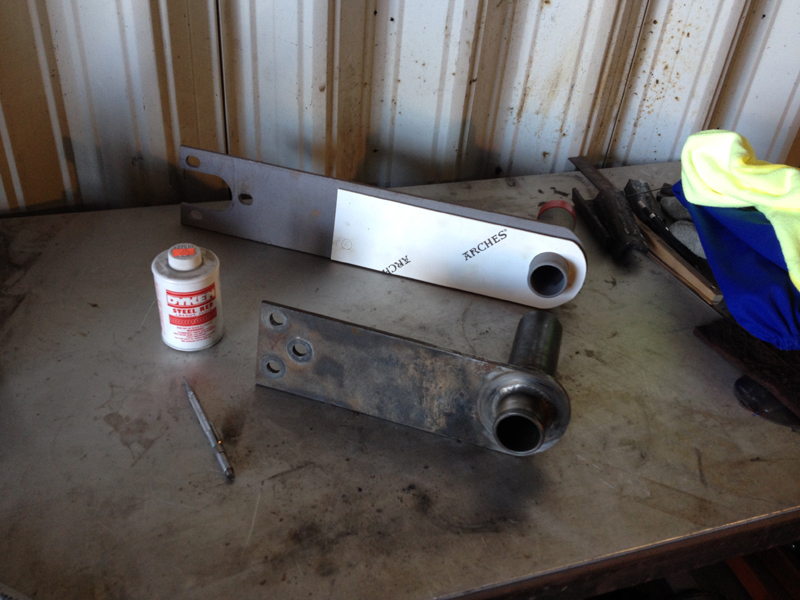
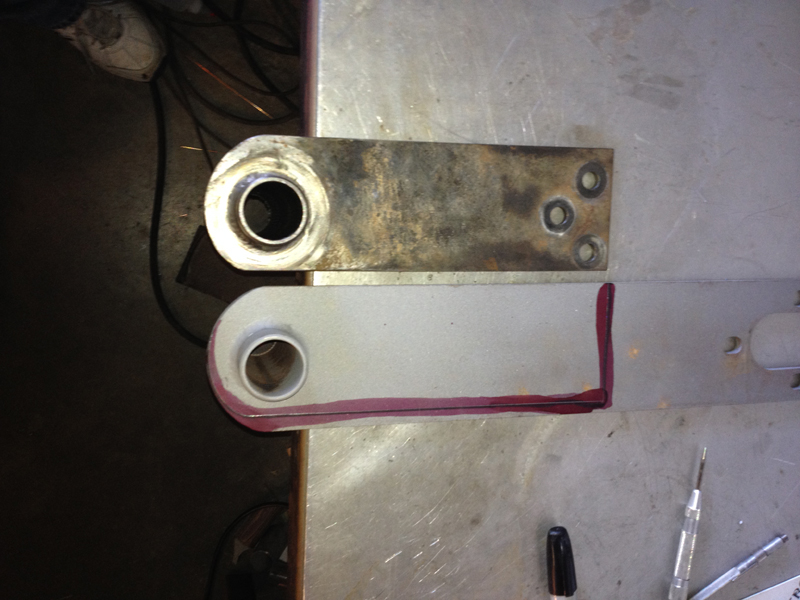
We created templates from the old spring plates, no reason to start from "scratch"! We use the template to identify how much needs to be trimmed from the stock "swing axle" spring plate and where to drill the holes. As you can see, the IRS spring plate is much smaller than the swing axle version behind it. We use the swing axle spring plate as a starting point because a stock IRS spring plate will not work with our +1" trailing arms (SCORE allows 5/1600's to run trailing arms 1" longer than stock). So, we have to custom make ours (SCORE allows us to use "any manufacturers" spring plates - we're the manufacturer.....).
Aside from cutting the new spring plate to the proper length, you might ask why we also trim the width (and why we do so asymmetrically)...... It's all about getting as much suspension travel as possible with a 5/1600 car.....
The new spring plates have been match drilled to fit the trailing arms, de-burred, trimmed edges polished, they've been "blacked" and had an anti-corrosion treatment applied - they're now ready for service.
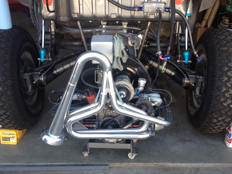
Engine Exhaust System The exhaust system on a 5/1600 car takes a lot of abuse; getting "nerfed" hard by a hyper-aggressive driver wanting to catch up to his class after a breakdown can destroy it in an instant (faster classes start ahead of us to reduce this problem but breakdowns occur frequently and we find Trophy Trucks and Class 1 cars behind us often). More commonly it gets dented during the disassembly process or just "wears out" ( race fuel seems to "eat" them from the inside out over time.....). We could just patch our exhaust system when problems arise but it's a critical part of the engine package whose failure could delay or end a race; we usually choose to replace rather than repair as a result. That seems like the more expensive option until you consider the cost of a race lost or "DNF'd" due to an exhaust system failure.....
This is the "standard" exhaust system that most VW 1600 motors use in desert racing and it works great. The downside is that installing it takes 4 hands and lots of patience...... These "race" engines have all been machined to increase their compression ratios; that narrows the engine a bit and makes the fit of the exhaust system difficult at best - getting everything lined up at one time is frustrating. Anti-seize compound helps everything slide into place; even so, it took me a couple of hours to get it installed without scratching it all up or pulling all the engine exhaust studs. It's like one of those wire puzzles that only go together one way.......
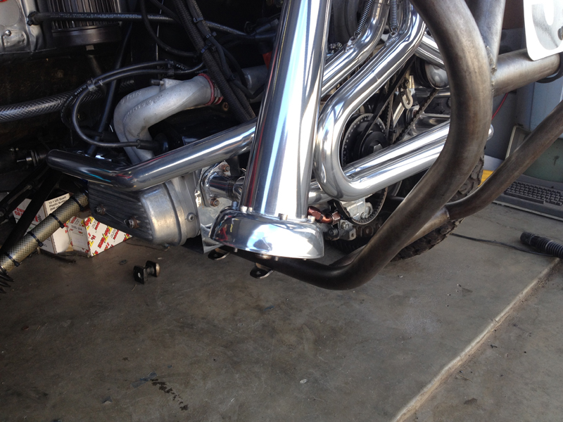
All desert racing organizations require a spark arrestor/muffler of some sort be part of the exhaust system. The "SuperTrapp" is the preferred option for most VW motors; it does both jobs with a minimum of horsepower stealing flow restrictions, added weight and complexity.
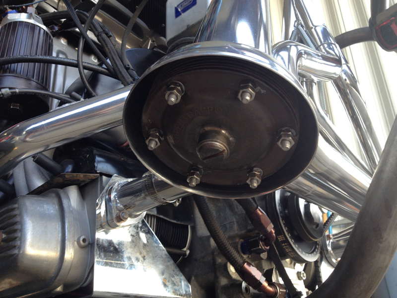
As you can see, the SuperTrapp is a series of stacked disks that permit the exhaust to escape through the gaps. It's possible to tailor (tune) the installation to your needs by adding or removing disks, adding washers between them, etc.. Everything is a compromise though; small number of disks and no washers - quiet but lots of restriction, lots of disks with washers between - loud but good flow..... We added the threaded boss in the center of the cap plate to allow us to insert an O2 sensor when we dyno. test.
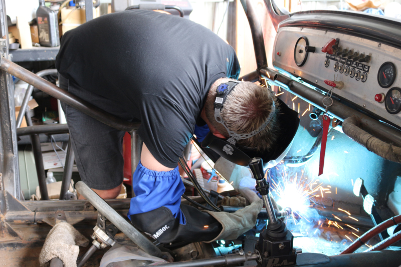
With the Frame Head repair complete, we can now begin to re-build the forward support structure. Rather than repair the old structure, we've elected to replace the entire assembly with new and heavier duty tubing. First step: remove the remnants of the old assembly from the main cage structure - that's all inside the driver/co-driver cabin so it'll require some disassembly there.....
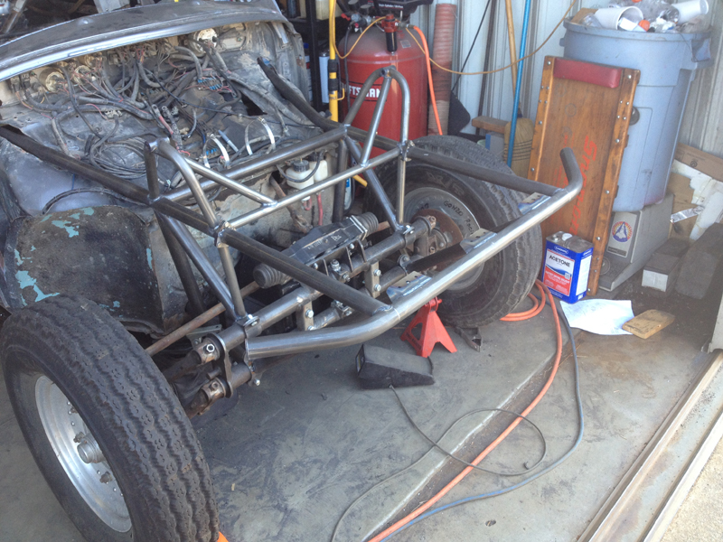
The front cage supports the entire front suspension system; it provides a secondary support for the suspension beam and the upper shock mount structure as well. The front cage must also support a spare tire and provide mount points for the hood, the front bumper and the Char-Lynn power steering unit. While the basic structure is coming together quickly here, there is still lots of "detail" work to do in support of those requirements.....
The basic structure is nearly complete; once we fit these support tubes, the beam support structure will be ready for the addition of all the other elements that support other needs.
Just a few more support tubes to install followed by "tabbing" to support the horns, lights, sheet metal, etc..
|
Overview and Checklist
Post Race Disassembly
Post Race Inspection
Repairs and Preventative Maintenance
CV Polishing and Prep.
Suspension Tuning
|
|