|
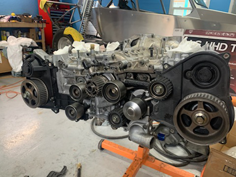
Valve train idlers and gears installed but not
yet aligned for belt installation
The crankshaft and both camshaft gears must be aligned correctly
for belt installation to ensure that the valve timing is correct.
|
 |
 |
 |
|
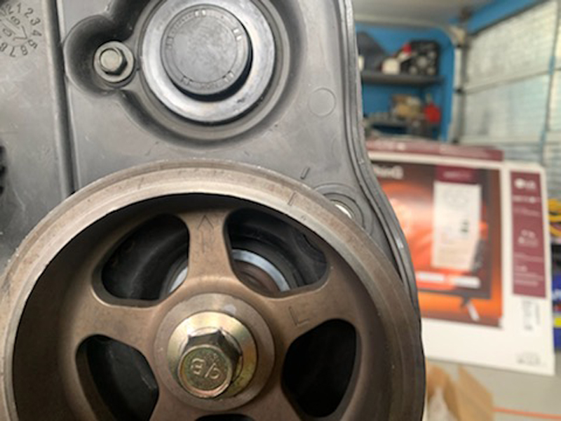
"Right" cam
pulley timing mark aligned |
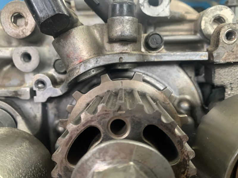
Crankshaft timing
mark aligned |
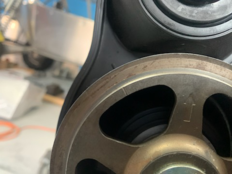
"Left" cam pulley
timing mark aligned |
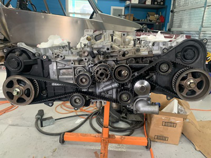
Valve timing belt installed and timed
correctly
The Subaru valve timing belt is marked so that once all
three drive gears are aligned with the case index marks, the
belt markings are then aligned with those same marks then the
belt is tensioned. This method ensures that the
crankshaft/valve timing is correct and is easily accomplished.
It's possible to install the belt "backwards" though so it's not
quite "foolproof"...
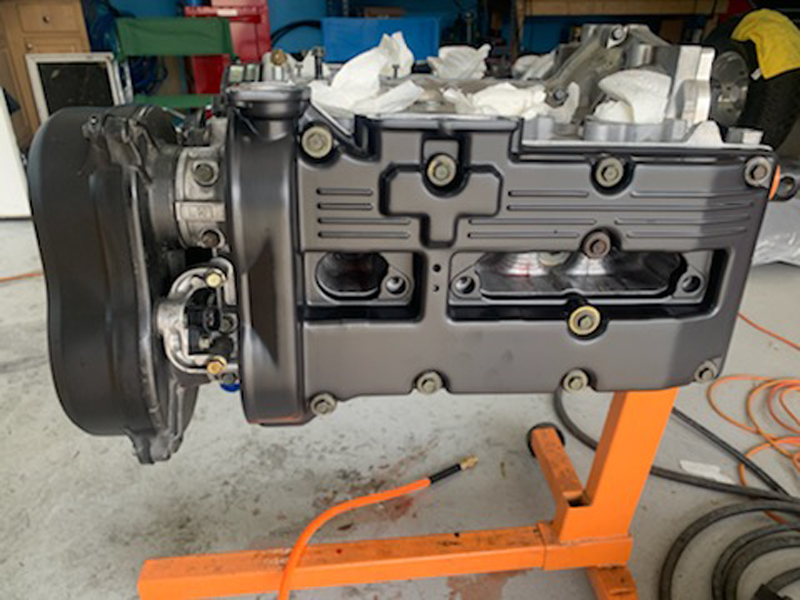
Valve cover installed
Now that the engine is
essentially in a "long block" configuration, we can begin to
install the accessories:
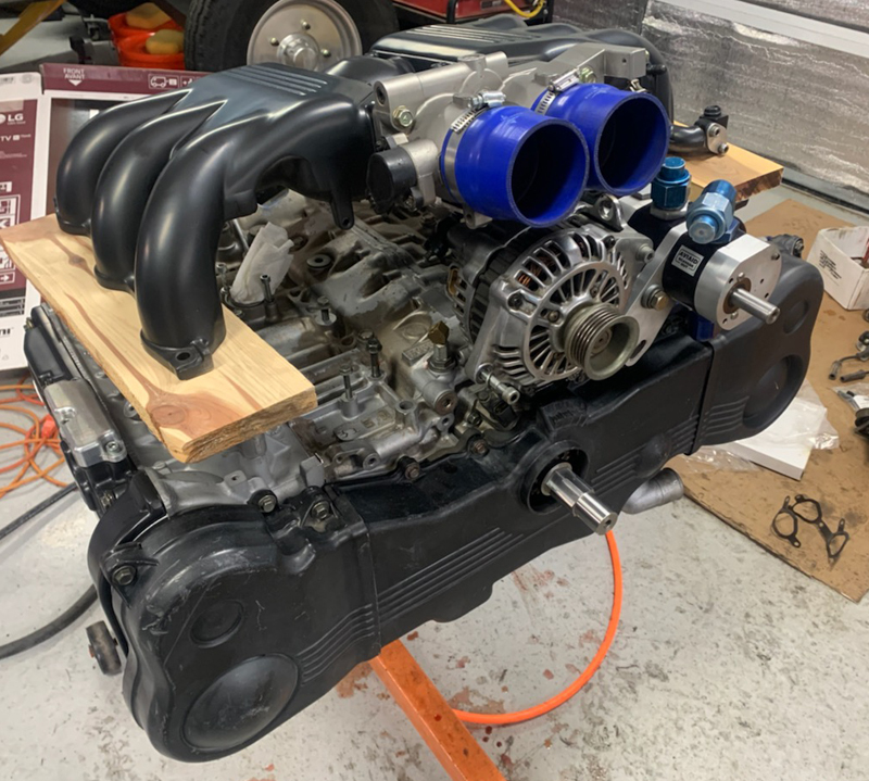
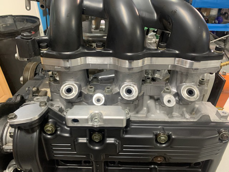
Mocking up the intake manifold and accessories
Normally, the intake manifold would be clocked 180 degrees from
the shown orientation. In our "rear engine" application, it's
necessary for us to install the intake in the shown orientation.
As you can see here, there is insufficient clearance between the
throttle body and alternator without additional spacers under the
intake manifold. The boards acting as spacers here are
approximately 3/4" thick but provide about 1/4" more space than we
need; we'll fabricate 1/2" spacers from aluminum for the final
install.
Intake manifold spacers we fabricated from 1/2"
aluminum plate
Spacer plates installed, intake manifold
secured
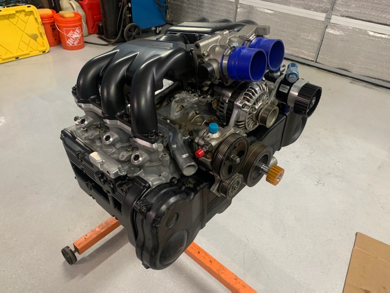
Here you can see the the intake
manifold/alternator proximity
Spacers fabricated and installed; we now have plenty of clearance
between the two assemblies in addition to a clear path for plumbing
the air filter(s).
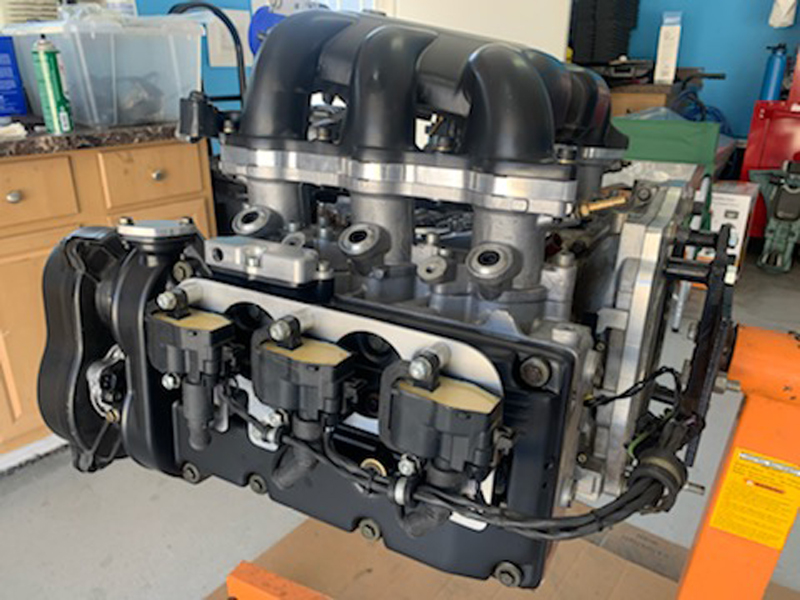
Ignition "coil packs" installed
Continuing the assembly; coil packs installed, injectors coming
soon and the ECU wiring harness to follow.
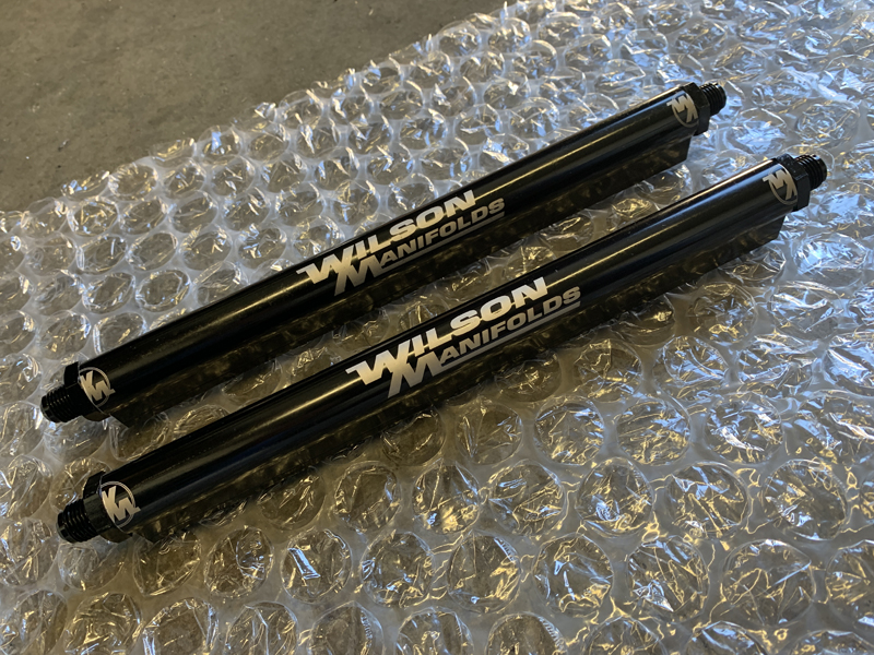
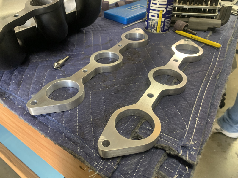
Custom fuel rails
We fabricated these custom fuel rails to replace the rails that
came with the engine. The supplied rails didn't have
provisions for retaining the injector "O-ring" seals - they had
smooth bore injector pockets that could allow the seals to "migrate"
off the top of the injectors, causing a major fuel leak and fire
hazard.
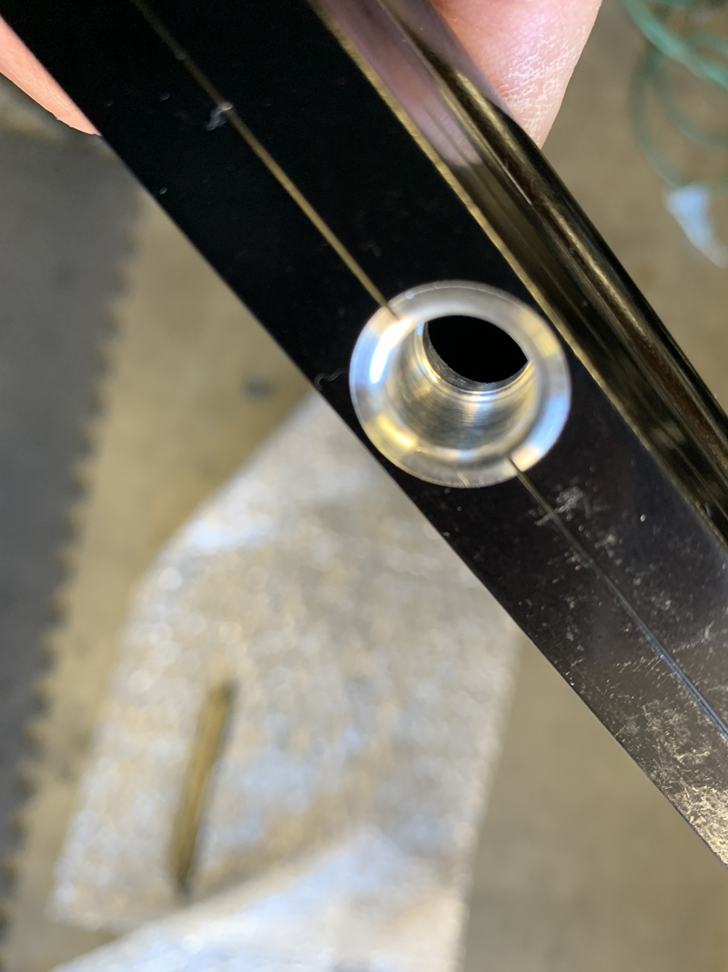
Properly machined injector pocket
We needed special tooling for milling the fuel rails correctly;
it consisted of a large (3/4-16) tap for the "O-ring" seal AN
fittings at each end and a custom tool for machining the injector
pockets. That custom tool made drilling the hole, step and
"lead-in radius" an easy, one step, operation. With the new
fuel rails correctly machined, the injector seals will be retained
from both the bottom and top, eliminating any possibility of them
"escaping" and causing a fuel leak.
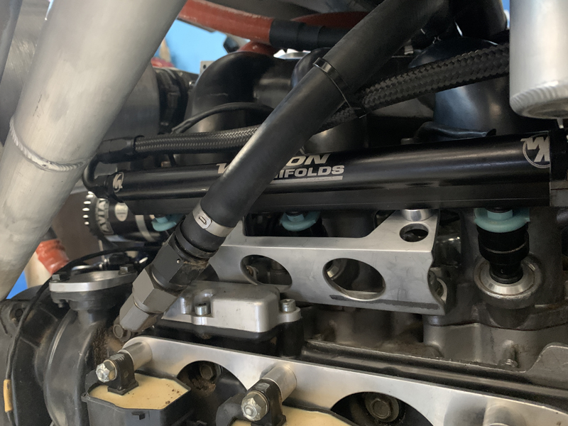
New fuel rails installed (Passenger side shown)
Our new fuel rails fit perfectly and are leak-free under
pressure. We were also able to eliminate the "sketchy"
features that bothered us with the previous rails; the new rails are
safer, more secure and easier to service. |