|
The Subaru EG-33 engine
is normally a "wet-sump" type engine - that system works fine
for vehicles run on pavement but has proven to be less reliable
in off-road conditions, leading to bearing failures. In
our pre-runner application, a "dry sump" oiling system is much
preferred. There are commercial "bolt-on" dry sump systems
available but we already have the "expensive parts" on hand
(they came ready for installation with the engine when we
purchased it) so we're fabricating the remaining parts we need
ourselves. Essentially, we do away with the stock oil pump
and oil pan in favor of a "dry sump" pump assembly that consists
of both a scavenge (oil return) pump and an oil supply
(pressure) pump. The scavenge pump continuously returns
the oil draining from the bearings to an external oil tank.
The oil tank feeds the input of the oil supply pump, insuring a
steady supply of oil to the engine.
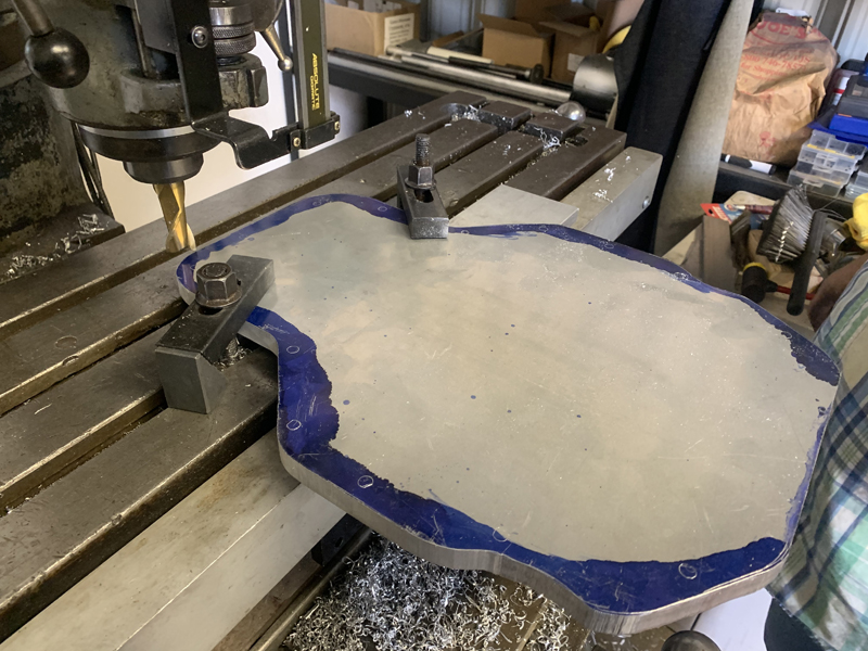
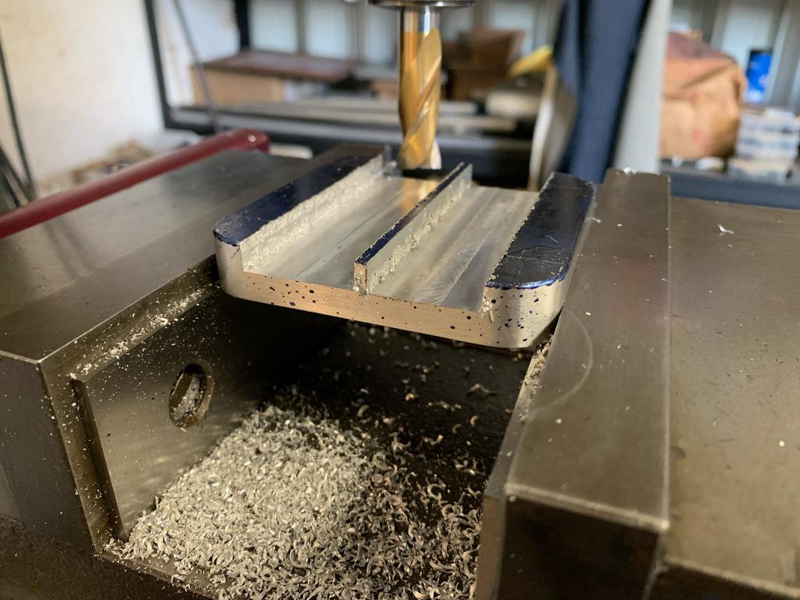
Dry Sump crankcase plate being milled to
shape
We eliminate the need for a stock oil pan; the oil supply
will be contained in an external tank. We still need to
close the gaping hole that would otherwise exist when we remove
the oil pan so this plate is needed to replace it. Here,
you see the sump plate being milled to shape. Next, we'll
drill the mounting holes and mill the "inside face" to direct
the draining oil to the scavenge pump pick up fittings.
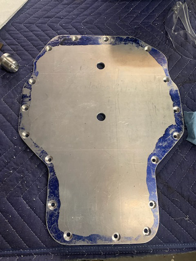
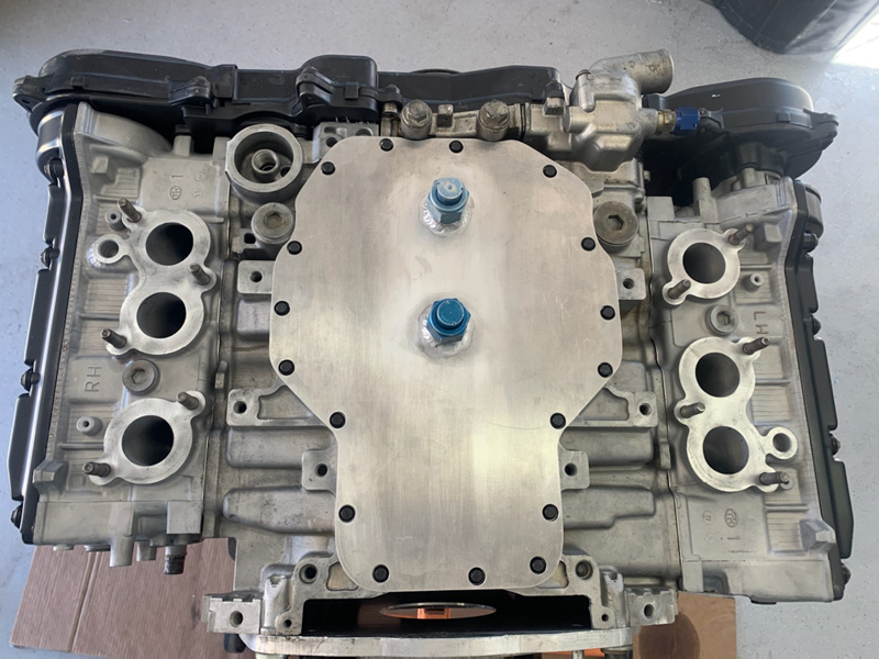
Sump Plate mounting holes drilled and
counter-bored
This is the "outside" face of the sump plate; the two large
holes near the center of the plate are where the scavenge pump
hose fittings (one is visible in the upper left corner of this
photo) will be welded in place.
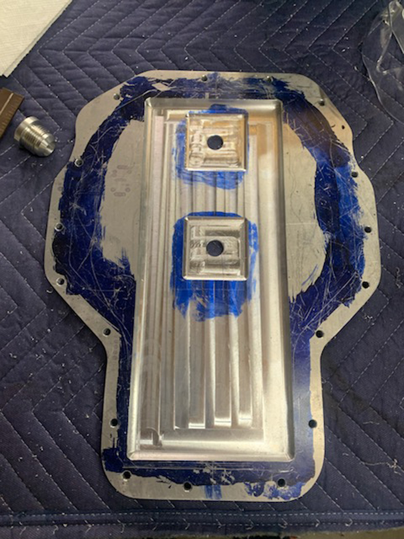
Sump Plate "inside" face milled to shape
We milled the inside face of the sump plate to help direct
the draining oil towards the scavenge pump pick up fittings.
The scavenge pump will ensure that very little oil collects
inside the engine - it will immediately be pumped to the
external oil tank for use by the oil supply pump. We
provided two pick up fitting locations but we have only one
scavenge pump circuit. We'll use only one of the pick up
fittings; once we determine which location works best, we'll
make the pickup connection there and the other fitting will be
capped.
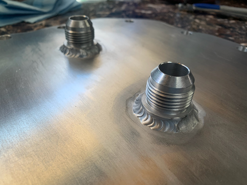
Scavenge Ports welded in place
Trevor welded these at home - it was a bit of a challenge
with his garage 220V circuit breaker limiting the current he
could apply...
Sump Plate temporarily installed to check
the fit
It looks like a good fit - now we just have to etch and
apply the Alodine "conversion" process then "final" install it.
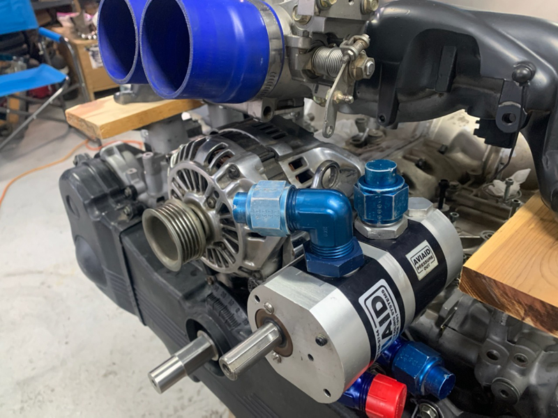
Dry Sump Pump
This is the "dry sump" pump that replaces the stock oil
pump. It's an external pump "assembly" with two
independent pumping sections on one shaft - one for "scavenging"
oil from the crankcase and returning it to the external oil tank
and the other for delivering oil from the storage tank to the
engine under pressure. The pump will be belt driven by the
crankshaft via the extended shaft seen protruding from the
plastic cover.
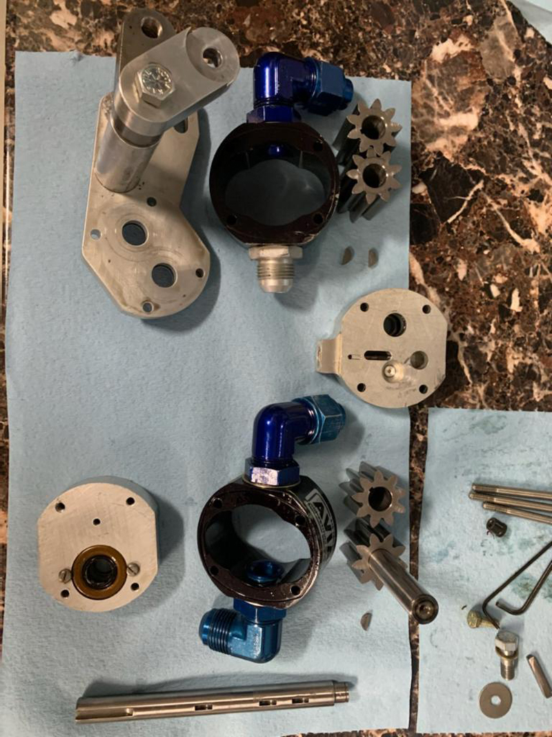
2-Stage oil pump disassembled for overhaul
The pump was missing seals and not correctly assembled when
we received it with the engine core. Trevor disassembled
the pump, inspected it and replaced all the seals.
Fortunately, aside from the missing seals, it was in excellent
condition. Once reassembled and installed, Trevor operated
the pump with a drill motor to verify function and check for
leaks. The pump was clearly working; the pressure lines
"flexed" and the oil quantity in the tank dropped as all the new
lines filled with oil.
To perform an initial oil pressure adjustment, we again used a
drill motor to simulate idle operation. We noticed that
the oil quantity in the tank didn't stay constant - oil was
accumulating in the engine sump faster than it was being
scavenged (the pressure pump is twice the size of the scavenge
pump). We installed an oil pressure test gage to see why
that might be; we found the oil pressure was quite high, leading
to the in/out flow imbalance. Fortunately, pressure is
easily adjusted via a bypass valve in the oil pump. With
the idle oil pressure adjusted to a "normal" range, the scavenge
pump now keeps the engine sump "dry" as it should when we turn
it with a drill motor.
With the engine running, we found that the
scavenge oil pump works fine up to about 4000 RPM but beyond
that point doesn't keep up with the amount of oil flowing into
the pan from the bearings. We believe that this is due to
a "vortex" being formed directly above the oil pickup at high
flow rates (high RPM's). The vortex allows air to be
entrained, reducing the scavenge pump's ability to keep up with
the amount of oil flowing into the pan... After
researching the issue, we believe the solution is to incorporate
"vortex breakers" into our oil pan.
They're essentially cover plates that only allow the oil to be drawn from around their perimeter
rather than from directly above the oil pickup fittings.
Milling the "Vortex Breaker" interior profile
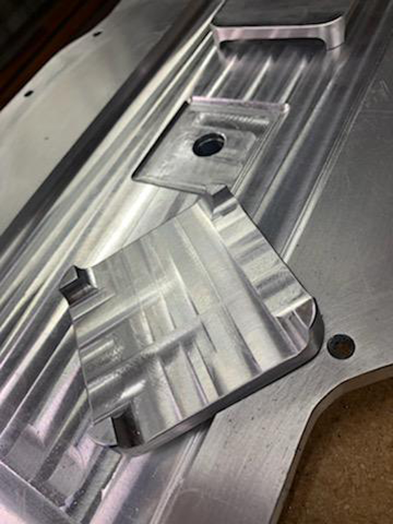
Milled to shape
These are simple parts; their only function is to keep the oil
flowing to the scavenge pump with a minimum amount of air
entrained. Obviously, if the scavenge pump keeps the oil
level below the top of the slots, air will be entrained - but
that's not a problem as long as there isn't a net transfer of
oil to the crankcase from the tank...
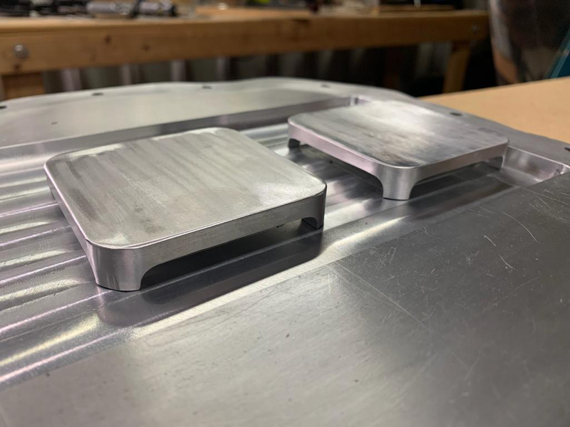
Vortex Breakers in position, ready for welding
Trevor will weld the Vortex Breakers in place over the scavenge
pump oil pickup locations. This design is essentially what
was recommended by the manufacturer of our dry sump pump; we
simply took the idea and scaled it to fit our pan. The
slots total nearly two square inches on each while the area of
the actual pickup is closer to .44 inches square. The
covers sit well above the actual outlet (there's a "well" under
each, not visible in this photo) and shouldn't cause any flow
restriction.
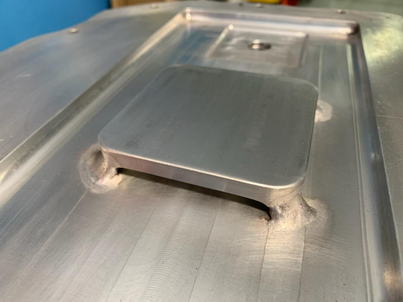
Vortex breaker welded to pan
We have a single stage scavenge pump so we can use only one
oil pickup location at a time. As the car's body angle changes (up
or down hill), the oil level will vary a small amount as a
result. We're consciously choosing not to manifold more
than one pickup port to the scavenge pump to avoid the scenario
where one port is "uncovered" while the other is submerged.
In that situation, rather than evacuating oil, the pump will
draw air from the uncovered port until the oil level rises to
cover both ports... The other pickup location visible in
this photo tends to be the "high point" in the pan on level
terrain and wouldn't help as a result.
In addition to the "Vortex Breakers", we
fabricated and installed a custom "Windage Tray" and modified
the stock oil pump to act as an additional "scavenge" pump.
We also re-configured the "dry sump pump" so that the scavenge
pump portion was the larger of the two pump sections. We now have good control of the oil flow through the engine and
back to the oil tank; the oil level in the tank and
crankcase stay within normal limits at all rpm's. |