|
An exhaust system that meets our needs is
not readily available commercially; we'll have to design and
fabricate our own. There are numerous considerations
including: fit, performance, sound, etc.. Trevor has done
extensive research and has identified the basic parameters; now
it's a matter of routing and mounting to be decided upon.
He has decided upon a "6 into 1" collector arrangement with a
single muffler to be located in the space behind the engine.
There are other systems that will need to be located nearby - we
need to be careful to consider their requirements... Once
the routing is determined, we'll start piecing together all the
bends and straight sections of tubing until we have the shapes
we want. This may be a bit of a trial and error process;
nothing will be final welded until everything fits as planned.
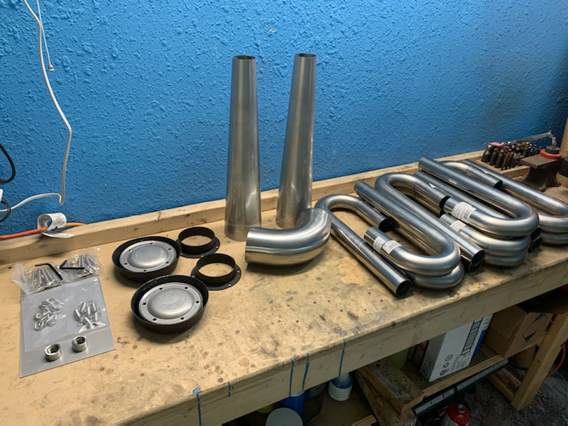
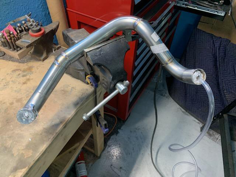
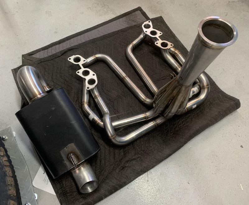
Raw components we'll use to create the exhaust system
These are just some of the stainless steel tubes we'll use
to create the individual exhaust tubes. They'll be welded
to exhaust flanges in groups of three; one "group" flange
per side. They will be routed low (but above the skid
plate) and then terminate behind the crankshaft pulley where
they will meet the "6 into 1" collector. The collector
will have a "V" clamp on the muffler side; that will allow us to
change muffler arrangements without any cutting/welding.
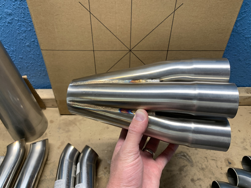
"6 into 1" collector
Rather than use two "3 into 1" collectors, we
are using a single "6 into 1" collector. The "slip joints"
will allow us to keep the left and right side manifolds separate
for installation, then combine them with this collector before
the muffler.
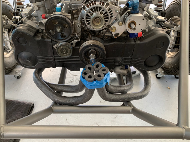
Exhaust system "mock-up"
This is a rough approximation of the desired configuration;
we'll de-conflict any problem areas during the actual
construction. We want all the exhaust tube to be equal
length and to be arranged in the collector in the most efficient
orientation - that's a challenging process but we'll get it
done!
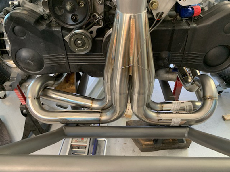
Exhaust System Fabrication
Routing all the tubes while keeping them the same length and
remaining within the confines of the cage is a challenge...
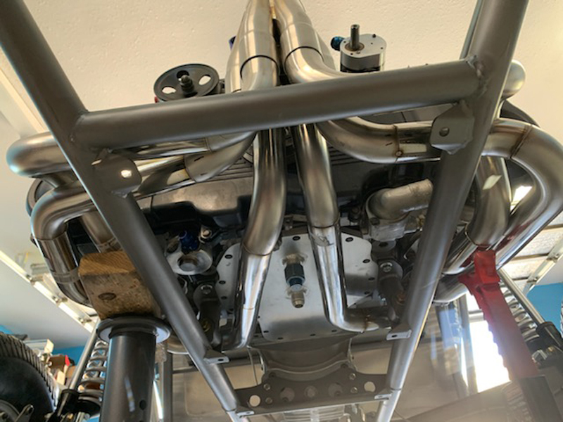
Bottom View
Welding one of the tubes
Each of the six individual tubes were custom fit to
the engine and the other tubes; this tube is being
final welded with an internal Argon purge gas supply.
Once all six are final welded, they'll be reinstalled and welded
to the engine exhaust flanges.
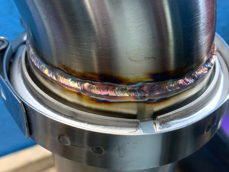
"V-band" joint between the collector of the muffler
We chose to include a V-band connection between the
collector and the muffler to allow us to try different muffler
configurations without the need to cut and weld.
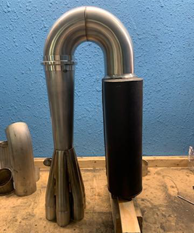
Initial Muffler configuration
This is the muffler configuration we are starting with;
we'll be able to easily change configurations later if we
choose. The outlet of the muffler will have an
elbow and "Supertrap" spark arrestor also.
Almost there
Just a little final welding to accomplish then off to bead blast
for uniform finish. The muffler is stainless steel so the entire
system will develop that stainless steel "patina" we like.
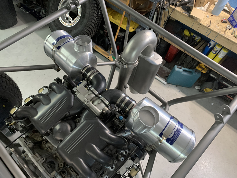
Engine air filter configuration
We experimented with several different air filter mounting
configurations; this one presented the best compromise in our
opinion. We wanted the air filters as close to the
throttle body as possible to minimize ducting losses, they
needed to be mounted securely, be easily serviced and had to
leave enough space
for the remaining equipment installations (oil reservoir, power
steering reservoir, etc.).
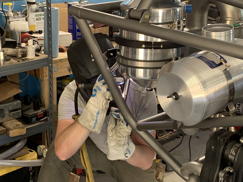
Trevor welding the oil tank support
structure
Our "Dry Sump" engine oiling system
requires an external tank to hold the oil; it needs to be
located near and above the system pump . This is a
convenient location that affords easy access for filling and
draining - it's also as close to the dry sump pumps as we can
get it...
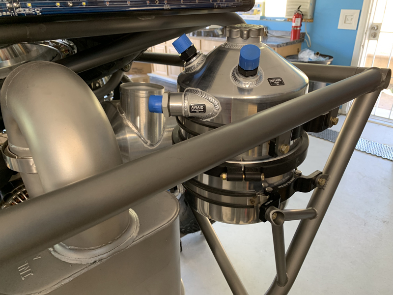
Mount fabrication complete
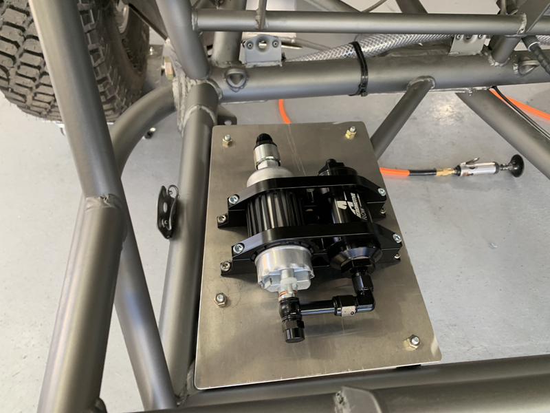
Fuel pump/filter assembly mounted
We mounted the fuel pump/final filter
assembly on an aluminum plate that's secured under the rear
seat. The plate is mounted to the chassis with rubber
"vibration isolation" mounts to minimize any pump noise in
addition to reducing wear and tear on the pump due to vibration.
Since this isn't intended to be a "race car",
we've chosen not to install a "back-up" fuel pump. We'll
carry a spare since failure of the fuel pump would otherwise
require recovery by tow or trailer... The assembly is
easily accessed and serviced by removing the body side panel - a
few minute job with a screwdriver...
|