|
We have five main areas of "plumbing" to
contend with: power steering, brakes and clutch, fuel, oil and engine cooling.
The power steering plumbing has been
partially complete for months. The control valve to steering
rack lines are complete and installed; the lines between the
control valve and pump were installed on the control valve and
left long for us to complete once the engine installation was
complete. We're now at that point.
We completed the brake and clutch plumbing
several months ago when we installed the pedal assembly.
We recently filled both those systems with brake fluid and bled
them until the pedals were firm and they seemed to operate
correctly. We've subsequently decided to change the clutch
master cylinder to a slightly smaller bore in order to "lighten"
the clutch a bit. The brakes seem fine at the moment but
we have a brake pressure gage on order to confirm that the front
and rear brake pressures are in the "ballpark" with moderate
pedal pressure. We can change those master cylinder sizes
if needed also.
Our fuel system is fairly simple; we come
out of the fuel cell to a "pre-filter", into the fuel pump, out
of the fuel pump to a fine "post-filter" then to the fuel rails.
To regulate fuel pressure, we come out of the fuel rails to an "Aeromotive"
fuel pressure regulator that returns excess fuel to the fuel
cell.
Our "dry sump" oil system is more
complicated than the "wet sump" system found in most autos.
Our engine doesn't retain any oil in the "sump"; oil is stored
in an external oil tank that collects oil "scavenged" from the
engine. That tank supplies oil to an external oil pump
that is actually two pumps in one; a "scavenge" pump that
recovers oil from the engine after it has done it's job and a
"pressure" pump that delivers oil to the oil filter then back to
the engine under pressure. This "dry sump" system will
ensure a constant supply of oil to the engine under all
conditions.
Engine cooling is accomplished by a large
radiator with electric fans located just above our fuel cell.
The radiator is supplied with "ram air" via a duct between the
roof and roof rack when the car is in motion and the fans when
the car is stationary. To compliment the radiator, we have
a "surge tank" in addition to an "overflow tank". The
surge tank serves to help eliminate trapped air in the cooling
system while keeping the coolant level full. The overflow
tank provides a place for excess coolant to be retained when
necessary. It's a fairly simple cooling system but will
require a little bit of fabrication to make everything work well
together. The plumbing will consist of 1 1/2" aluminum and
silicone tubing with a few smaller fittings required for
connecting the surge tank.
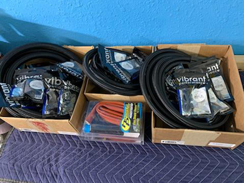
Some of the fittings and hoses we'll use to
plumb the fuel and oil systems
Rather than order custom made hose
assemblies for all the different connections we need, we chose
to order the necessary fittings and bulk hose so that we can
fabricate our own custom hoses.
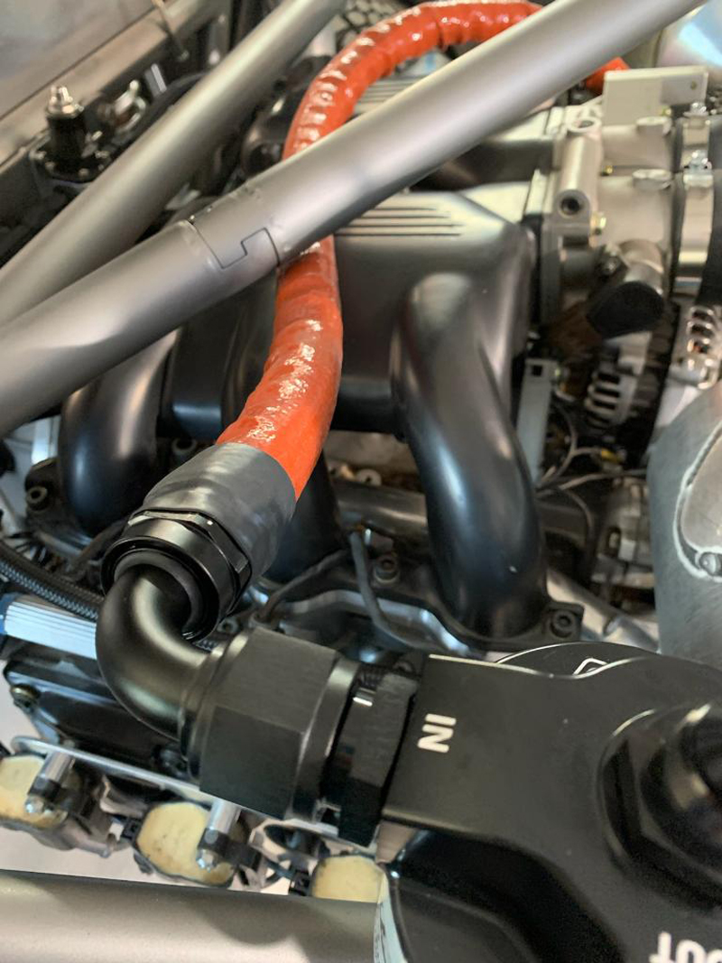
Oil pump to oil filter adapter hose
assembly
We installed a "fire sleeve" on this particular hose for
abrasion resistance more than fire resistance.
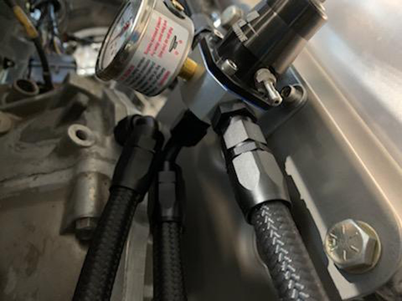
Fuel pressure regulator
Filtered fuel is supplied directly to the fuel rails from
the fuel pump; this device, also connected to the fuel rails,
bleeds off excess fuel and returns it to the fuel cell,
regulating fuel pressure as a result. This assures a
constant, stable supply of clean fuel at the correct pressure
while reducing or eliminating the threat of "vapor lock".
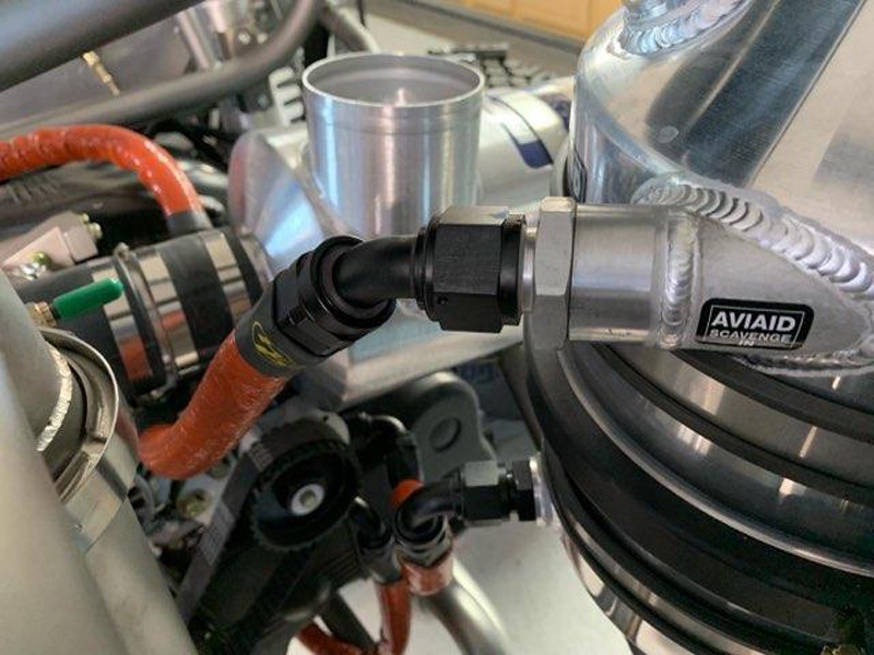
Dry sump system plumbing complete
All the hose assemblies for the oiling system are now
complete and temporarily attached. We still need to flush
and inspect each one, then final install them. Given the
proximity to the engine and exhaust system, we elected to "fire
sleeve" all the oil hose assemblies.
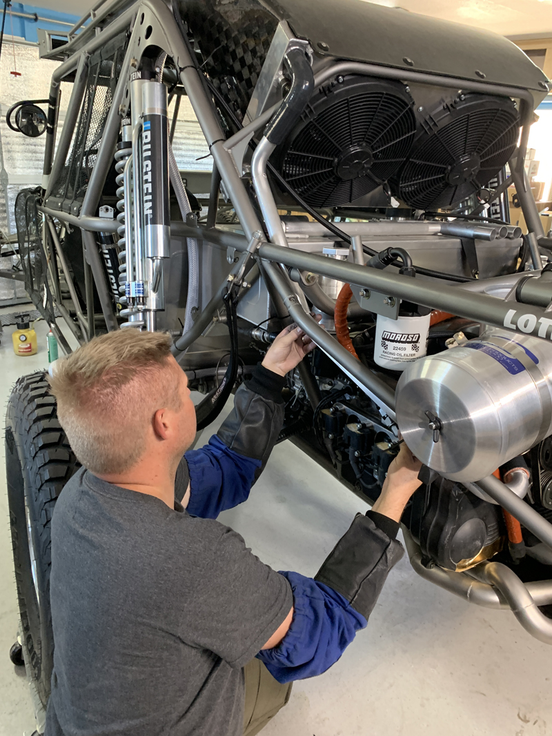
Trevor fabricating cooling system hard
tubes
Trevor started with 8' of straight aluminum tubing and a few
pieces of bent aluminum and silicone tubing. He then
pieced it all together to fabricate the two main coolant tubes
between the engine and radiator
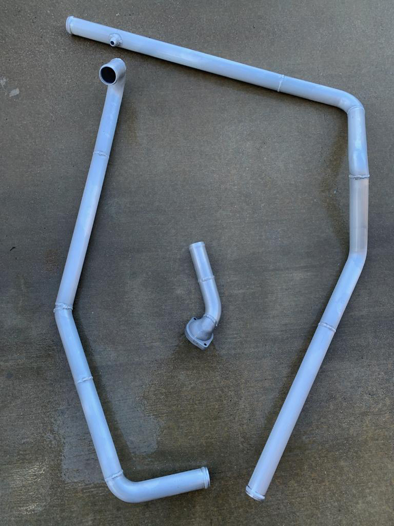
Coolant tubes
and thermostat housing leak/pressure tested
Trevor had to modify the thermostat housing in order to
clear the exhaust headers. Once everything was welded, he leak
checked each tube and made small weld repairs as necessary.
He then etched (you can see the powdery residue on the tubes)
and "Alodine" treated all the aluminum tubes for corrosion
protection.
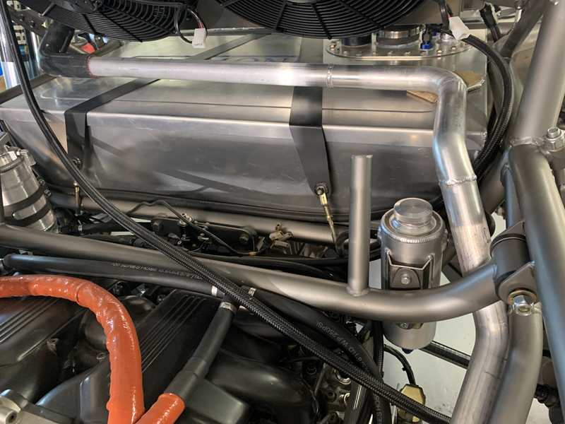
Engine coolant inlet line fitted
This is the line from the radiator that feeds the engine's
coolant pump. It'll be supported/secured in several
locations to ensure there are no chaffing, bending or vibration
issues.
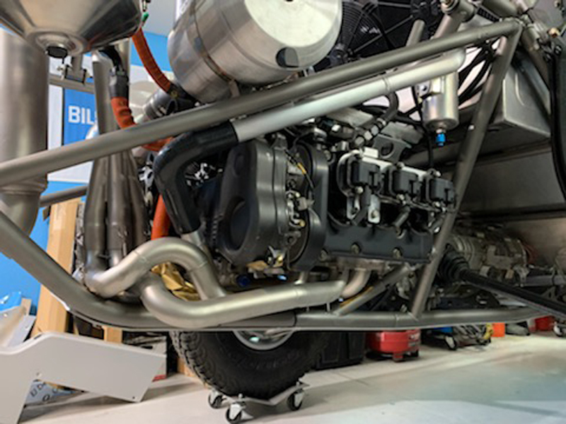
Inlet line connected to the thermostat
housing
The thermostat housing needed to be modified a bit to clear
the exhaust manifold with plenty of room. Trevor cut the
stock housing then added sections of bent aluminum tube to
create the shape we needed.
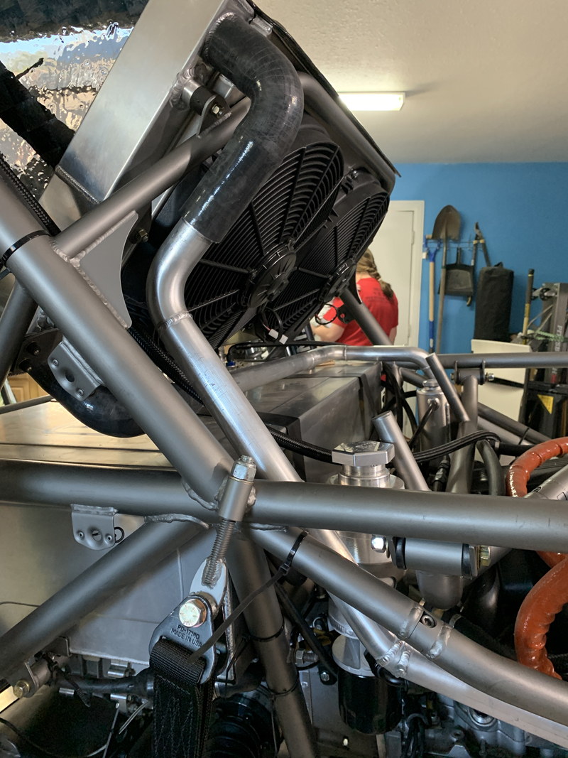
Radiator return line fitted
This tube returns hot coolant from the engine to the
radiator.
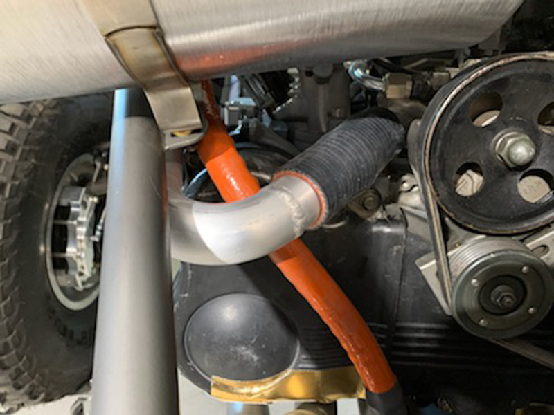
Radiator return line engine connection
We chose to run the hard tubes along the bumper tubes as
much as possible. That gives us an easy solution for
securing the tubes, keeps them somewhat protected and keeps them
situated as "compactly" as possible. "T bolt" clamps to
come next.
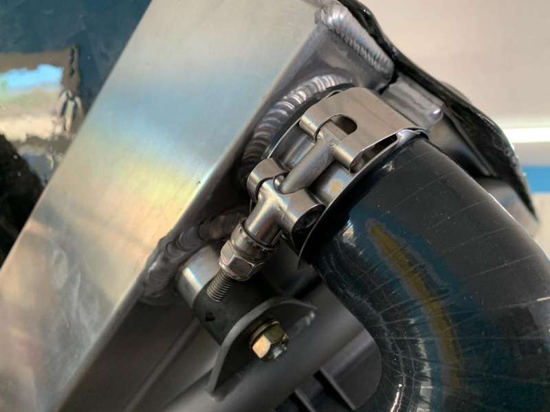
"T bolt" clamps installed
We had several different options for securing the cooling
hoses to the radiator and engine; "crimp" clamps, "hose" clamps
and "T bolt" clamps. We want the system to be serviceable
in the field so "crimp" clamps are out of consideration.
"Hose" clamps are easy but they tear up hoses and look cheap.
"T bolt" clamps are the most secure option and they don't tear
up the hoses - that's why we chose them. The only
down-side is that they're expensive. Fortunately, we only
needed a total of eight...
|


