|
We've installed our
Fortin 2.5 power rack and attached the tie rods we fabricated a
while back; now we need to connect the steering rack to the
power steering control valve and the steering wheel.
That'll require a little problem solving and fabrication; the
problem solving involves routing the steering shaft from a
steering wheel comfortably located for the driver, past the
brake pedal without interfering with it, to the control valve
and then to the power rack. Along the way, we had to
fabricate and install bushings for the provided steering column
mount and also need to fabricate and install a mount for the
steering control valve. Simple enough but we really need
the brake and clutch pedal assemblies installed to insure
the steering shaft doesn't interfere with them. The
chassis is set up to
use CNC brake and clutch pedals; even though CNC closed up shop,
we were able to find the correct pedals in stock at McKenzies -
our favorite off-road supplier. We now have all the
steering and pedal components on order; once they arrive, we'll
get to work fabricating the remaining steering system elements.
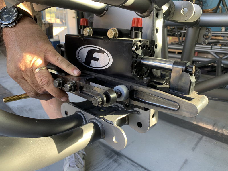
Installing our Fortin 2.5 Power Rack
We still need to replace the hydraulic fittings with 90
degree elbows - we have the correct fittings but we need to
remove the rack from the chassis to install them...
Tie Rods installed and roughly adjusted
We also fabricated an identical spare to carry strapped to
the chassis
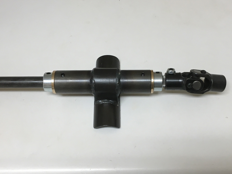
The steering column assembly, now ready to install
The above tubular weldment was supplied with the chassis, we
built it into to a "steering column assembly" with the
fabrication/installation of bronze bushings, set screws,
collars and a universal joint. This assembly can either be
welded or clamped to the chassis in our desired location and
orientation. We left the steering wheel end of the shaft long
for now so we can trim it to
length for driver comfort (once we determine where
that location is). We'll mount the brake pedal and
steering column assembly then locate and mount the control
valve. Once that's in position, we can fabricate the remainder of the
steering shaft.
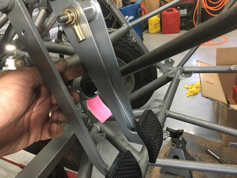
Checking the routing of the steering shaft
for Brake Pedal clearance
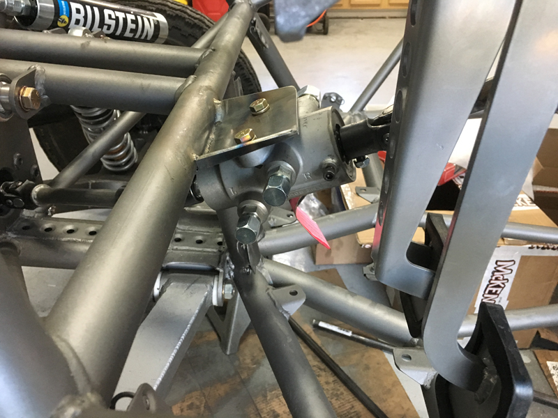
We spent at least an hour looking at various mounting
locations for the steering control valve; we were looking for
the best compromise between all the many factors - minimizing
universal joint angles, making sure that we could actually
install and remove the valve without cutting anything, ensuring
that there was room for the hydraulic lines, that there was no
interference with the pedals, etc.. We've seen other
examples of this car that have the control valve mounted a
little higher than the location we settled on - we really didn't
like the u-joint angles between the control valve and steering
rack that resulted when we mocked that up.....
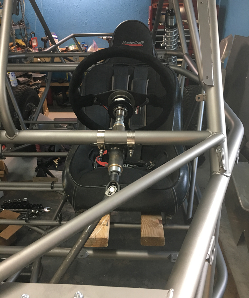
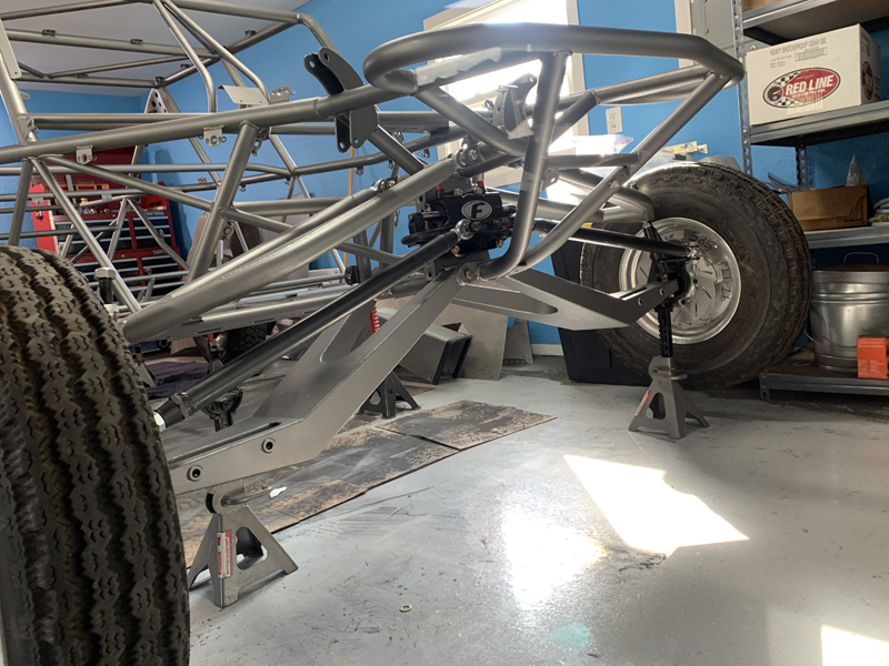
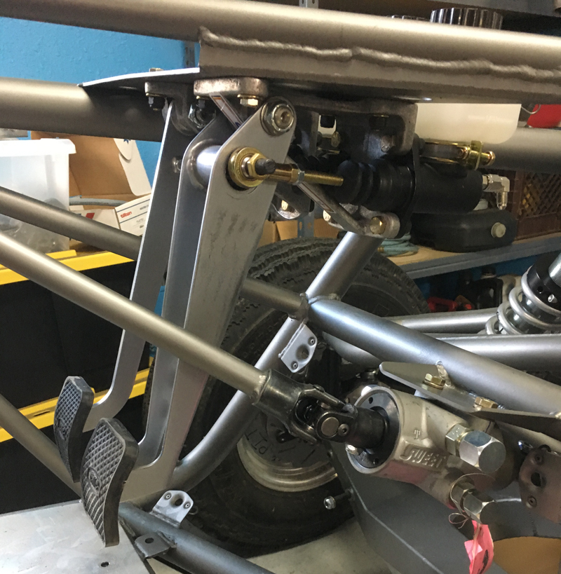
Steering wheel and shaft mounted
We borrowed a seat from our 5/1600 car so we could
simulate the driver's seating location while deciding where the
steering wheel should be located both left-right and
forward-aft. The camera angle distorts the perspective -
the wheel was directly in front of the driver with the seat in
the correct location. Trevor says that the location we
settled on is perfect. You can see the universal joint
angle here is fairly mild - the steering wheel/control valve
shaft operates smoothly without slop. We'll install the
steering column mount more securely than shown here once we are
absolutely sure we like how it's positioned.
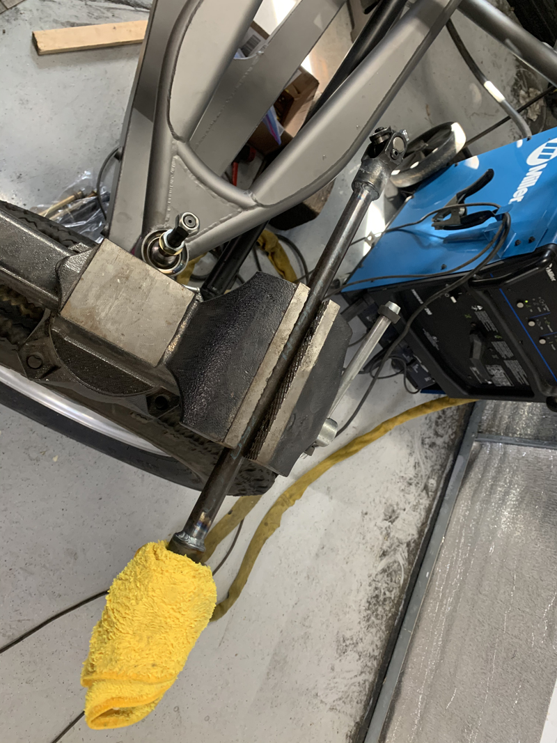
Universal joints welded on a
steering shaft section
After determining the correct length for the steering wheel
column/control valve shaft, we welded the universal joints in
place. We wrap the joints in a wet rag while welding so
that we don't overheat and ruin them. We didn't make the
control valve/rack shaft this day; the fit of the rack end
universal needs some finessing first... We need to remove the
rack anyway to install the correct hydraulic fittings so that'll
be on our list of things to do next time.
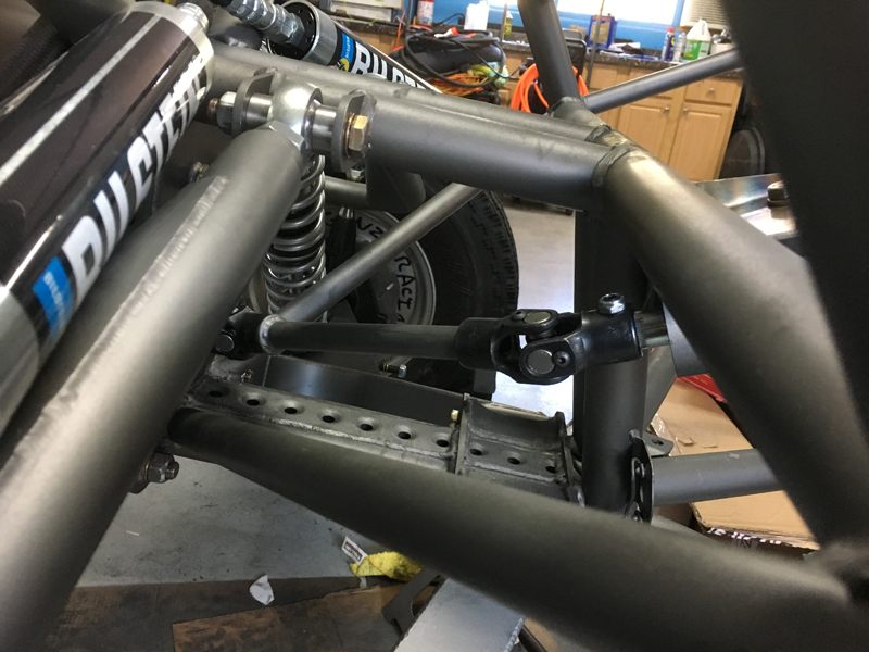
Final steering shaft section fabricated and
installed
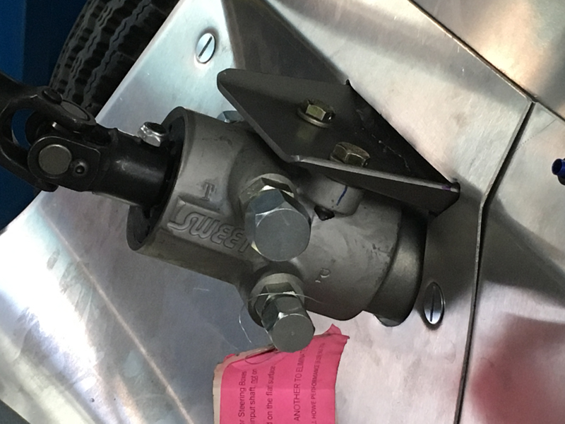
Steering control valve and shafts installed
This photo is a little deceptive - the brake pedal is well
clear of the control valve and does not interfere throughout
it's entire range of travel. The pedals are "hanging"
about where they'll "bottom-out" the master cylinders. The
throttle pedal will be installed later and will also have plenty
of clearance. Other examples of this car place the control
valve on the top of the tubular member; we chose to locate it on
the bottom of the same member to improve the steering shaft
universal joint angles after investigating the potential points
of interference. We're very happy with the installation;
it's "slop free", smooth and secure.
Foot well area sheet metal trimmed to fit
around control valve
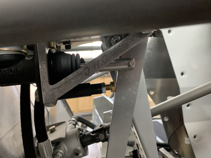
Brake and clutch master cylinders installed
With the master cylinders installed, we were able to
adjust the push rods to get the pedal positions we wanted and to
verify that full travel is available without interference of any
sort (it looks tight but there's plenty of room for my big feet
without coming anywhere near the steering shaft or valve).
Now that the master cylinders are installed, we can begin
installing the brake and clutch lines. The clutch line is
easy - no light switches or residual valves. The brakes
are a bit more complicated; we need a "residual valve" on the
rear brakes and we want brake light switches on both the front
and rear brake circuits. The turning brake unit will also
need to be mounted and have lines routed to it and from it to
both the left and right rear brakes separately.
Clutch pedal "stop" installed
It's important to limit the clutch pedal travel to avoid
over-actuating the clutch pressure plate and thereby damaging
it. We machined this assembly to act as an adjustable
stop; it replaces the nut securing the clutch master cylinder to
the pedal assembly and is easily adjusted as required.
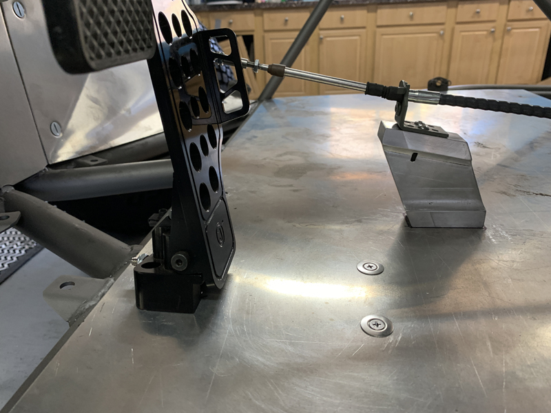
Accelerator Pedal and Throttle Cable
The gas pedal is a commercially available unit but the
throttle cable mount isn't. We milled the mount from an
aluminum plate after making a template to insure the shape and
location were correct.
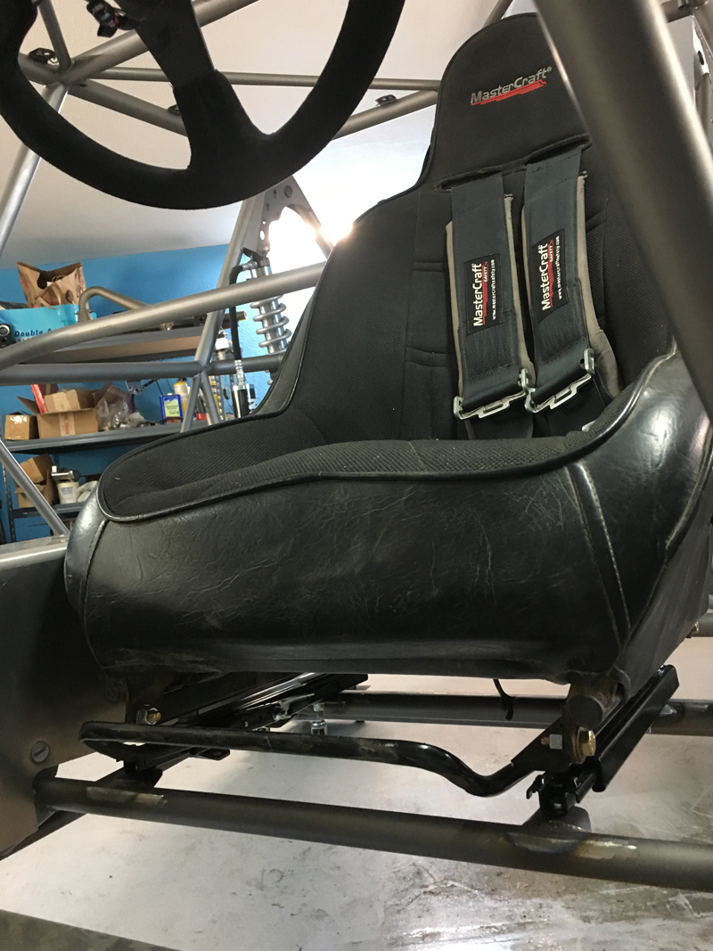
Driver's seat installed on "sliders"
We wanted the driver's seat to accommodate drivers of
varying size so a "slider mount" was needed. We chose the
"towel bar" style slider rather than the "side lever" type for a
number of reasons, including ease of adjustment and security.
The photo is deceptive - there is 1 1/2" clearance between the
seat and the center "tunnel".
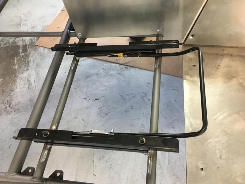
Passenger side slider base installed
We installed an identical slider base for the co-driver -
it's not absolutely necessary but it might make it more
comfortable for the co-driver.
|