|
The transaxle is the biggest single expense
in the build (aside from the chassis itself) so we needed to
budget and save for it... The build finally reached the
point where we could go no further without it so we had "Power
Box" (Rick St.John at Hugo's European in Encinitas, CA.) build
us a new "Weddle S5" sequential transaxle. Rick has taken
care of our 5/1600 transmission since our first few races; he's
really good and a friend - that made asking him do the build an
easy choice! The current "Covid 19" pandemic has affected
production and availability with wait times in excess of 6
months in some cases. Rick really came through for us and
we had our transaxle within two weeks of giving him the "Go
Ahead"! We can't thank Rick enough!
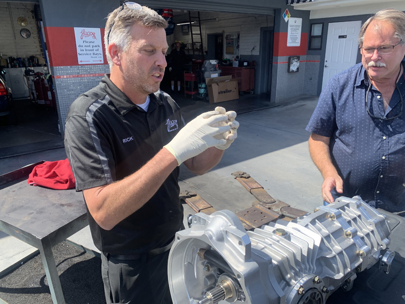
Rick and our Weddle S5
We've never had a sequential transaxle previously so Rick
was kind enough to spend time answering our many questions.
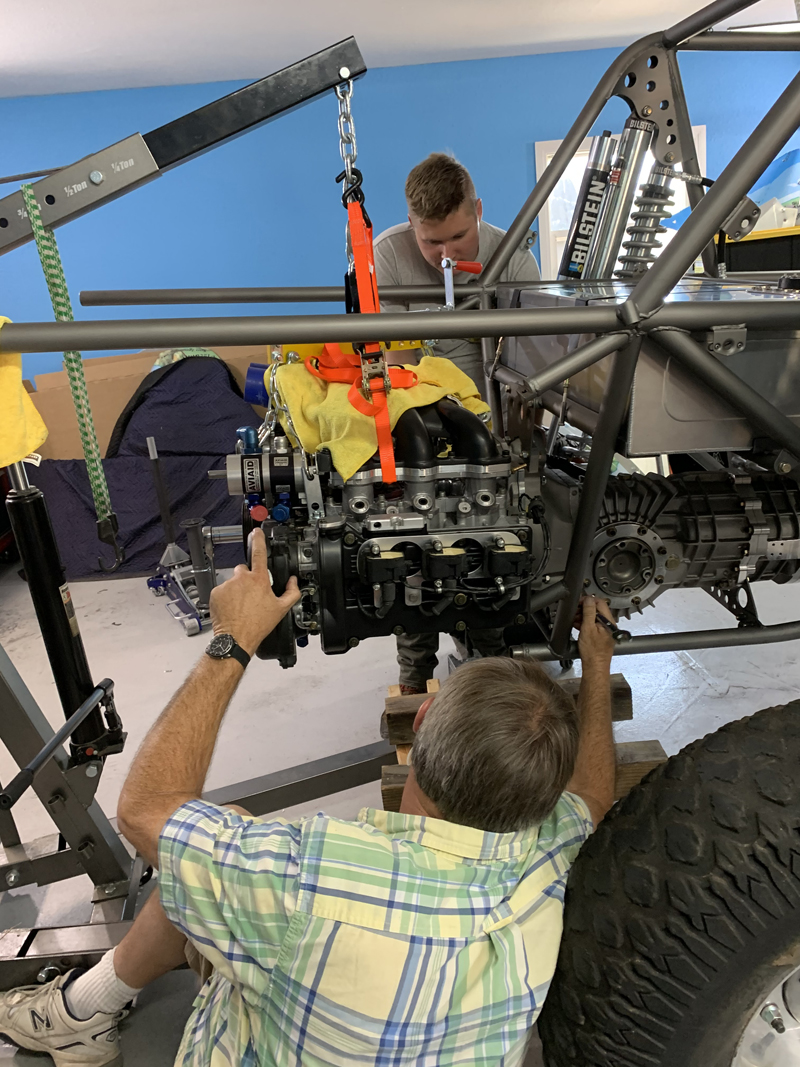
The old guy on the right is me...
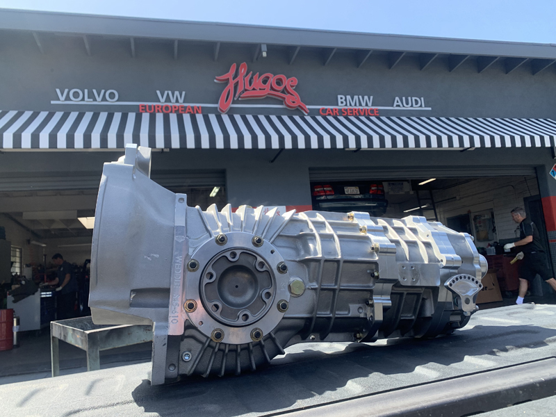
It's almost too pretty to put in a desert
car...
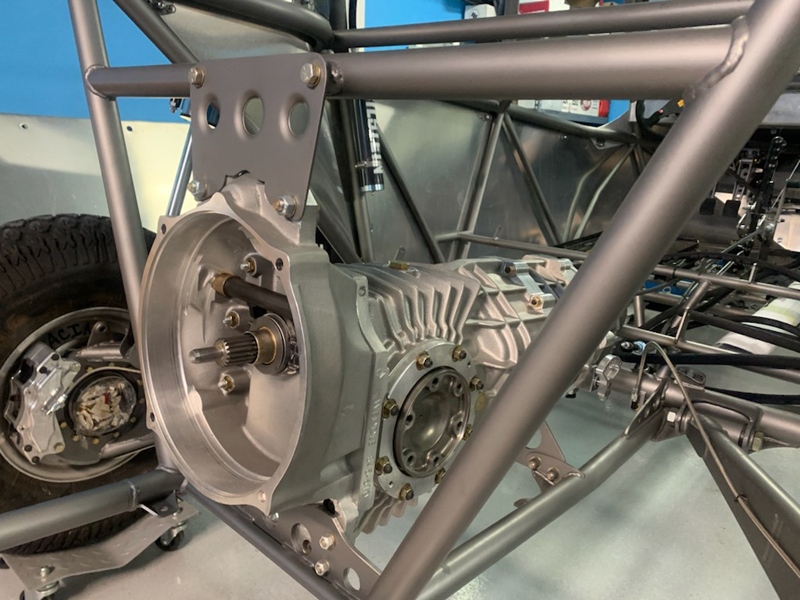
Bolted in to the chassis
Trevor wasted no time getting the
transaxle bolted into the chassis. We have lots to do now;
shifter hook-ups, clutch slave cylinder installation, CV and
axle selection/purchase/installation, gear position indicator
installation, etc. There are many other things we can work
on now; engine installation, fuel cell installation, radiator
installation, plumbing, electrical, exhaust, etc..
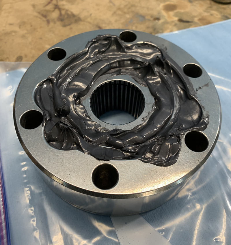
Transaxle 934 CV greased
Both the transaxle CV's and Mid-Board hub CV's were fully
greased during axle installation; hopefully they'll be happy for
many outings before we have to service them!
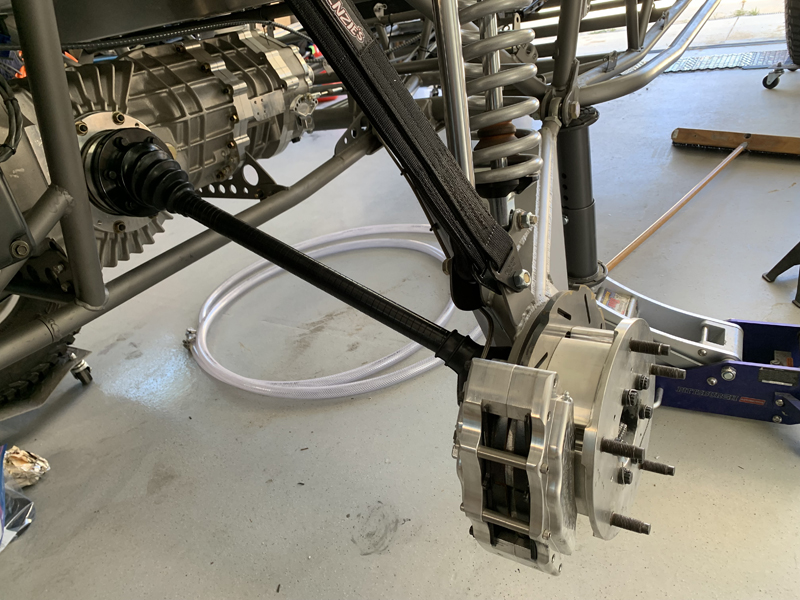
Axles, CV's and Limit Straps installed
Drive line fully complete now. We have our limit
straps set to allow no more than 24 degrees of CV angle
presently - we have the ability to increase or decrease that
easily. At this deflection limit, everything rotates
freely without any binding and the CV's should be "safe".
The CV's can probably permit a little more suspension travel but
we're being conservative - we can't really replace a broken
Mid-Board CV in the field...
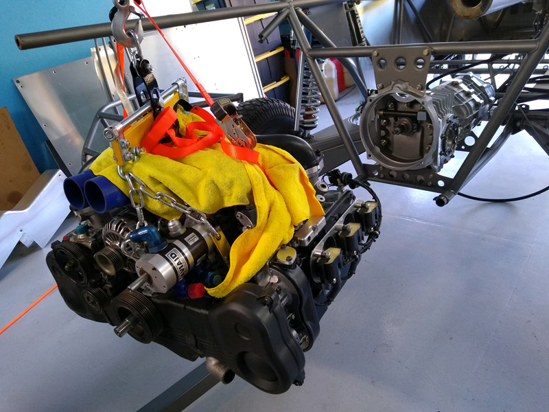
Hoisting the engine onto the transaxle
Engine bolted up to the transaxle
Fabricating engine mounts
We didn't want to rely solely on the transaxle for engine
mounting so Trevor fabricated a pair of these mounts.
We'll add a diagonal support tube in order to stiffen the mount.
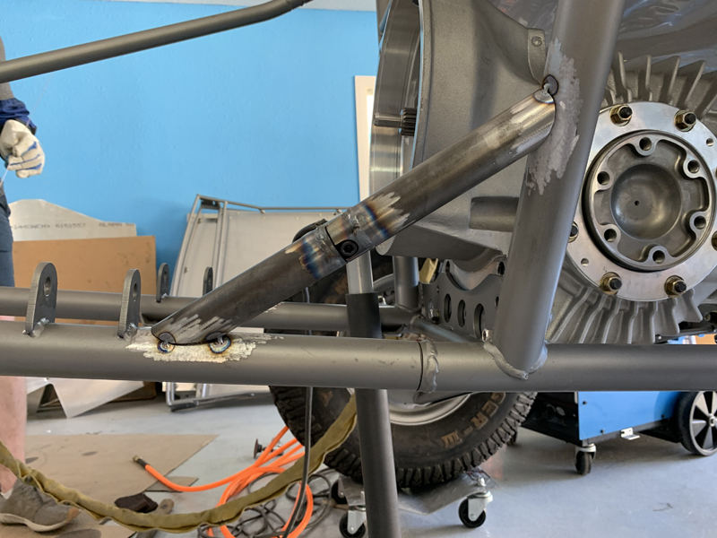
Passenger side diagonal support tube tacked
in place
The support tubes were fitted while the engine was installed
to ensure a good fit. With the engine removed, they were
fully welded in place. As you can see, the supports have
"tube connectors" installed. While not ideal, we needed
them so that the rear cage structure remains "removable".
We felt it was important to add these supports because
otherwise, the engine mounts would transfer loads perpendicular
to the middle of a long, straight tube...
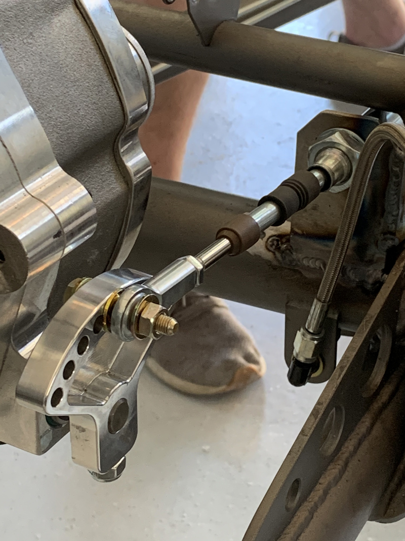
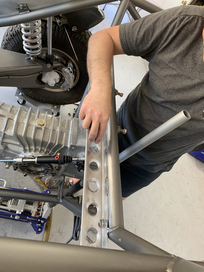
Shift cable mount fabricated and installed
Once both ends of the shift cable are secured, the shift
cable can be attached to the transaxle and the function of the
shifter tested. Shifting seems positive and normal at this
point. The "non-locking" nut securing the shift cable to
the transaxle is temporary; we'll replace it once the transaxle
is "final" mounted.
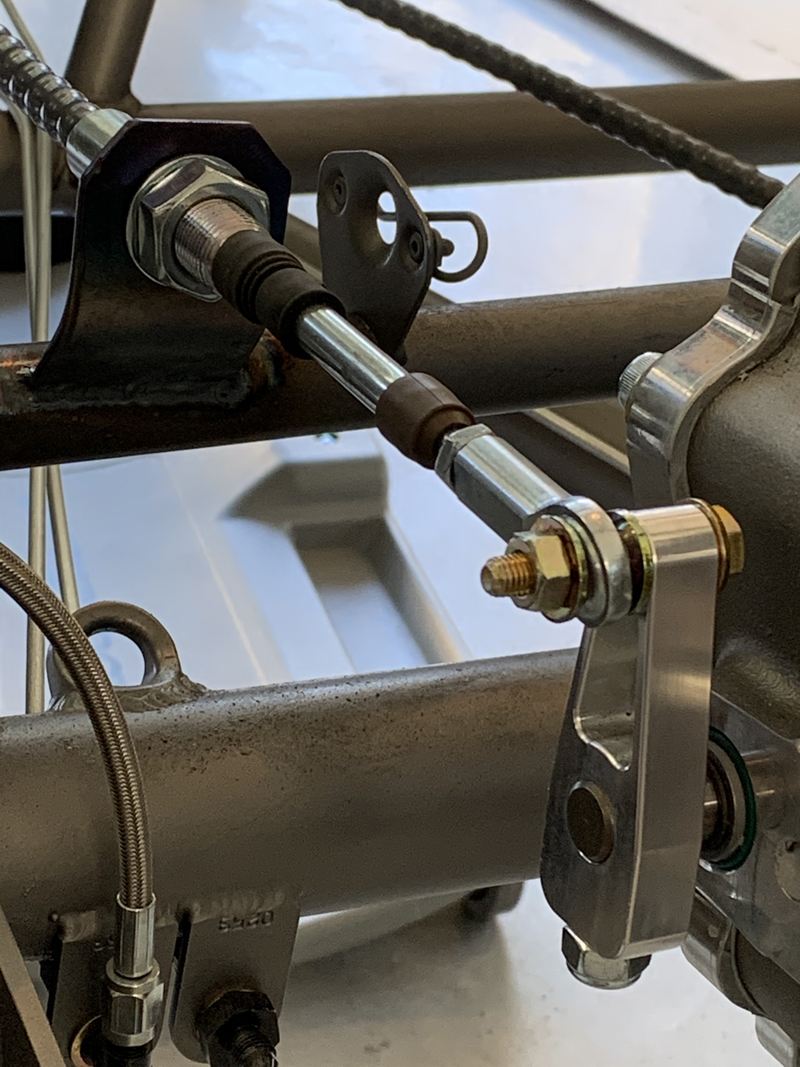
"Reverse" cable secured and attached to the
transaxle
As with the shifter cable, once the reverse cable housing
was secured at both ends, we were able to connect the cable to
the reverse lever and test the function of our shifter's reverse
lever - it worked perfectly. Again, the non-locking nut is
temporary.
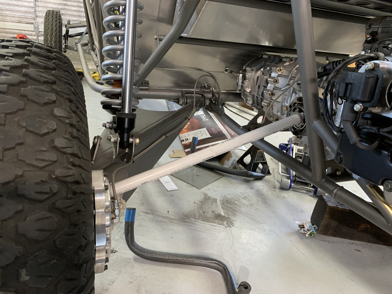
Measuring for axle length
While at "full droop" (25
degrees CV angle) we measured the minimum "clip to clip" length
required to keep the axles from pulling on the CV stars.
While there, we also measured for limit strap length; the straps
will keep us from going beyond the CV's safe angular limits.
After measuring the minimum axle length (1/4" more than the clip
to clip length), we cycled the suspension to "mid-travel" to
measure the maximum allowable axle length. The maximum
axle length is limited by the drive flange at the transaxle and
the dust cap at the wheel's CV. We need axles that are
long enough to allow full droop without "pulling" on the CV
"stars" but not so long that they bind with the drive flange and
dust cap at mid-travel. The left and right sides were
slightly different but we'll be able to use a single length axle
for both sides without issue - 33 1/4".
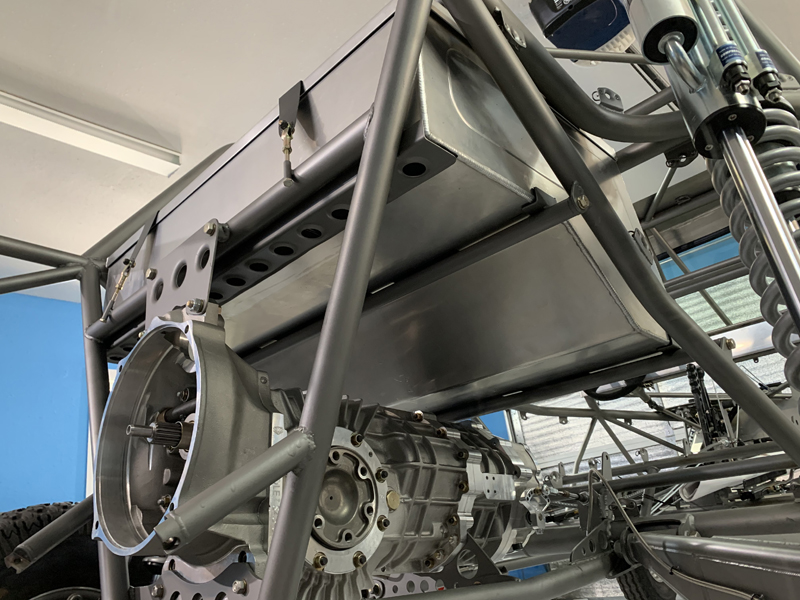
Rear fuel cell mounting "tray"
This tray supports the rear of the fuel cell and is not
removable. The front supports will be removable to
facilitate initially getting the fuel cell into the space and
will then be installed under the cell. Yes, we know the
clutch slave cylinder isn't oriented with the bleeder valve "up"
at the moment....
Fuel Cell mounting "mock-up"
The fuel cell is sitting on the rear tray but is supported
with temporary spacers between it and the transaxle so that it
sits at the correct height. We'll fabricate supports for
the front and middle of the fuel cell, ensuring that the loads
are distributed evenly. Those supports will be removable
to facilitate installation of both the transaxle and the fuel
cell. Once in place, the supports will be installed from
below and the fuel cell strapped down.
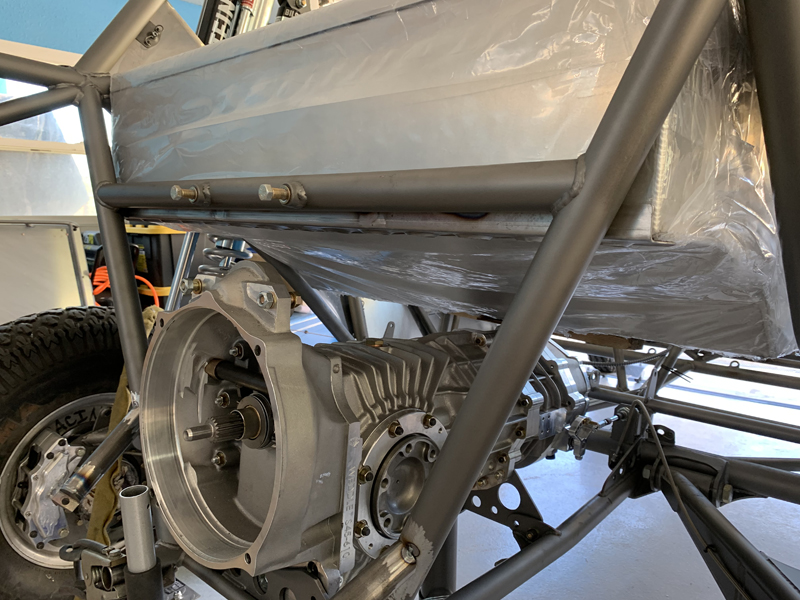
Fuel Cell location
The fuel cell resides above the transaxle and behind the
rear seats. It's a tight fit and the fuel cell supports
would also interfere with transaxle installation - that's why
they need to be removable. Our plan is to weld tabs to the
chassis that allow us to bolt the support structure under the
fuel cell once it's installed.
Fuel Cell support tubes
We fabricated two "cross tubes" that support
the fuel cell at the front and center locations in addition to
the rear "tray" visible here. To avoid "point loads" on
the fuel cell, we fabricated small "L" brackets and welded them
to the tubes - they help distribute the loads along the edges.
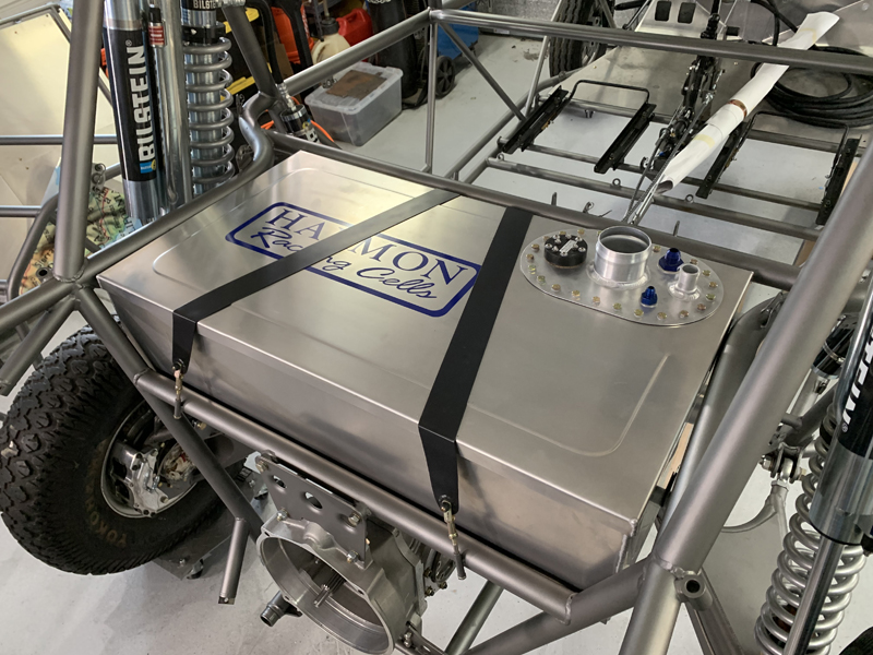
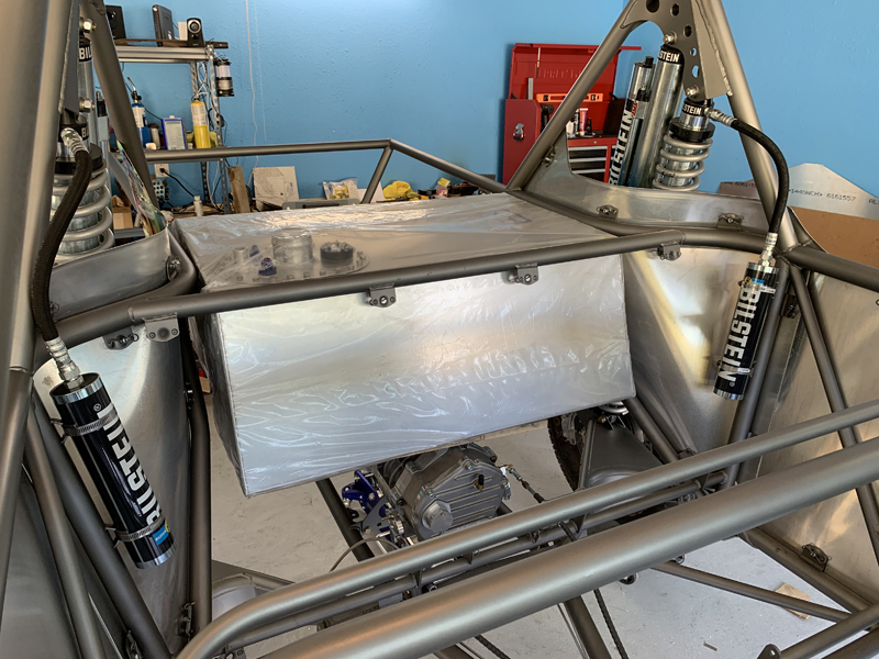
Fuel Cell "strapped down"
We fabricated 2" wide 4130 straps that bolt to the chassis
at the front and are tightened at the rear with clevis and bolt
assemblies. It's very secure but will be easy to remove.
You can see that the fuel cell is a tight fit between the upper
chassis tubes - we've installed leather strips between the tubes
and the fuel cell to reduce chaffing.
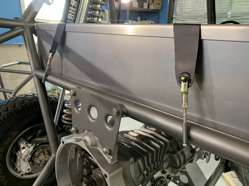
Clevis and Bolt Assemblies
These "clevis and bolt" assemblies allow us to
secure the rear of the retention straps and adjust the tension
in the straps as well.
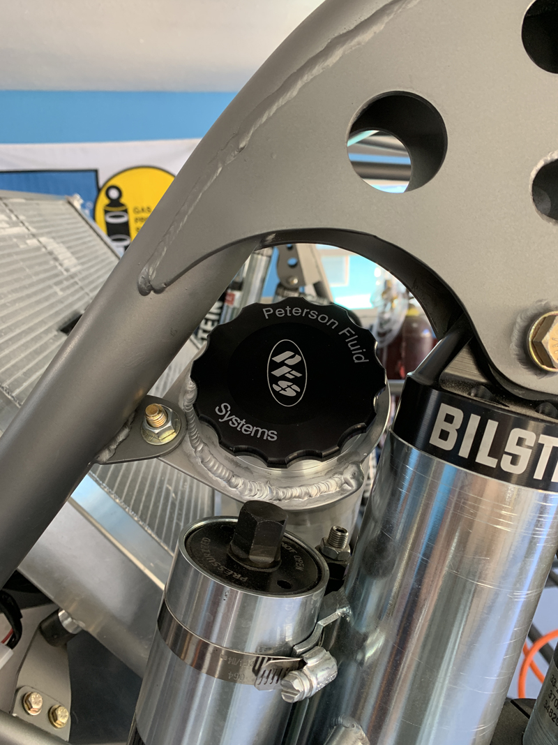
Fuel filler cap mounted
The fuel filler cap assembly is easily
accessible and remains clear of the shock as it cycles normally.
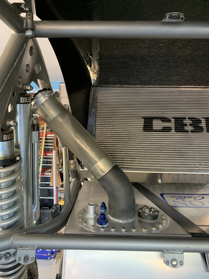
Fuel filler hose assembly fabricated
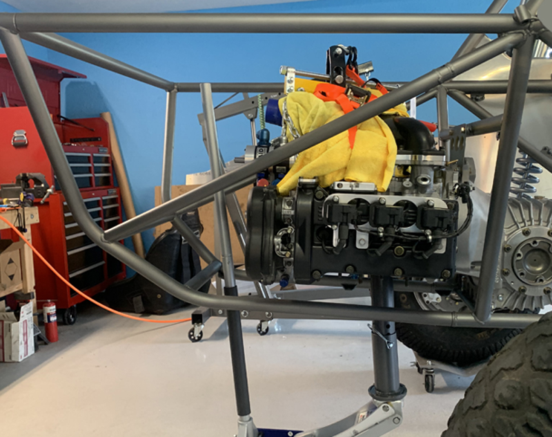
"Final" installing engine
With the fuel cell final installed, the transaxle and engine
could also be installed. With the engine and transaxle
finally in place, we can begin fabricating all the other details
- throttle cable, oil reservoir, air filters, power steering
reservoir, etc..
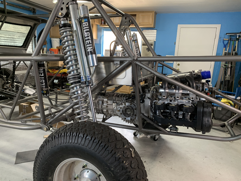
Fuel cell, engine and transaxle final
installed
All the major drive train components are installed now.
Still lots of work to do before the first run!
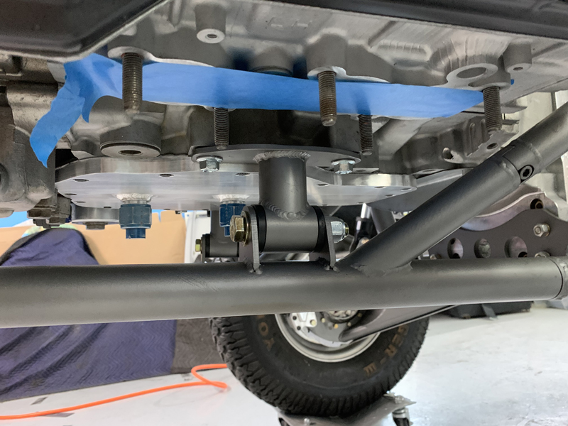
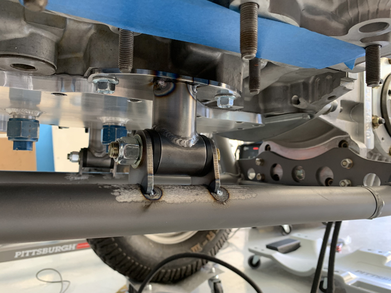
Supplemental engine mount
We didn't want all the weight of the engine supported by the
transaxle "bell housing" so Trevor fabricated these supplemental
mounts. Not wanting to apply a load in the middle of an
unsupported tube, we also added the diagonal you see here (one
on each side).
|