|
We've elected to fabricate and install the
electrical system ourselves for a number of reasons including
cost, time and the ability to create exactly what we want.
We have some experience in the subject and don't believe that
we'll regret this choice later...
We'll be using high quality components and
wire throughout and will endeavor to complete the job to a high
standard of durability, reliability and function. Some of
the work is already done for us; the engine came with a "Sakata"
harness tailored for it and a MoTec ECU. We'll only need
to plug all the connectors into the correct sensors and supply
power, ground and an ignition switch input. We chose to
purchase a "Switch Pros" 9100 - an eight circuit electronic
switch/relay/circuit breaker unit that eliminates the need for
us to create all those systems... We'll still be
responsible for all the basic things; radio, GPS, intercom,
lights, starter, etc..
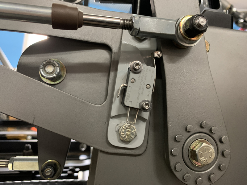
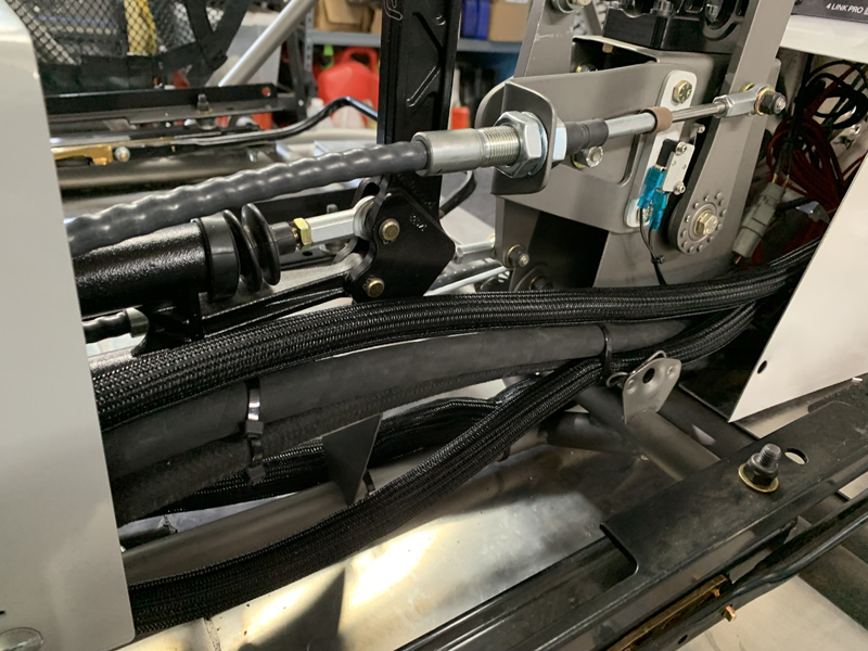
"Reverse" micro switch
We mounted this micro switch to sense when the transaxle is
in reverse. Our rear tail light unit has white "back up"
lights that we want to use and the transaxle gear position
indicator can also display "R" when triggered to do so.
This micro switch will control a relay for the actual load
switching; it's own contacts aren't rated for the required
amperage but can easily control a relay for working loads.
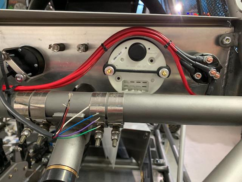
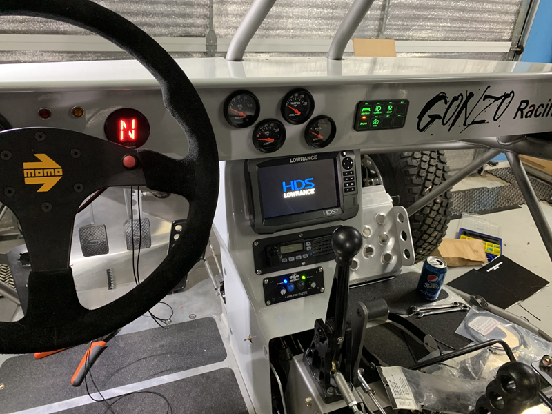
Ignition switch wired
This photo is of the early stages of wiring the dash - we
still need to wire the instruments and "idiot lights". The
challenge is keeping it neat, orderly and secure while ensuring
that everything works as expected. The multi-conductor
wire visible is for the gear position display - we'll be
installing a 6-pin connector on it to mate to the cable that
comes from the "sender" mounted to the transaxle.
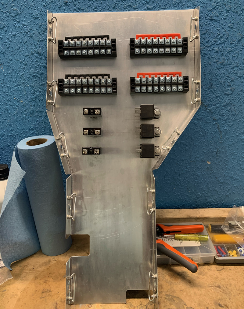
Center Console "Back" Panel
This panel closes out the center
console on the "back side" (towards the front of the car).
We've chosen to mount all the terminal strips, relays and
circuit breakers (aside from what's contained within the "Switch
Pros" unit) here for easy access and neatness. None of the
wire, relays or terminal strips will be visible once the center
tunnel and console are final installed; it'll still be easily
serviceable when necessary. We'll have a terminal strip
for the ignition "RUN" items, one for the ignition "ACC" items,
a "LIGHTS" bus and a "GROUND" bus. The circuit breakers
protect the powered buses and the relays are for the horns,
reverse (back up) light and manual control of the radiator fans.
The Switch Pros unit handles all the other switch, relay and
circuit protection requirements.
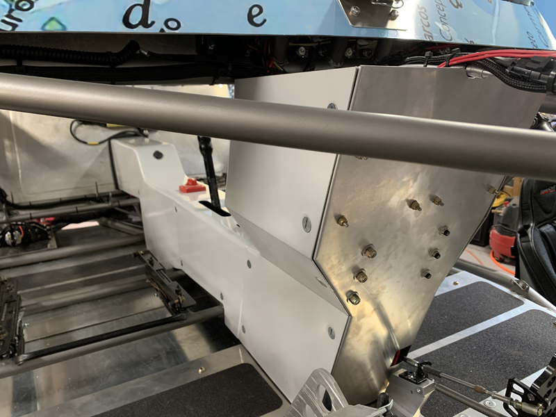
Center console back panel installed
With the back panel installed, all the bus bars, relays and
wires are contained inside the center console. This makes
for a tidy installation that's easily serviceable when
necessary. Visible are the three circuit breakers that
protect the "Run", "Acc" and "Starter" buses. All the
other circuits are protected by the "Switch-Pros SP9100" unit.
It takes the place of conventional switches, relays and circuit
breakers for up to eight individual circuits. We're using
only five of the eight circuits for now but plan to expand in
the future (fresh air pumpers, rock lights, etc.).
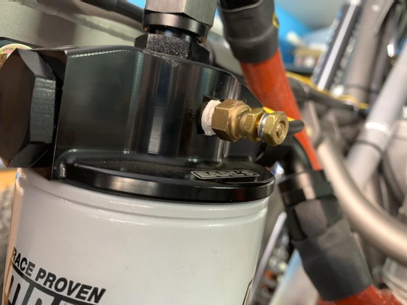
Oil Temperature Sender
All of the engine information "senders" are "one wire"
senders. Each sender has a single wire going to the
respective gage which also has power and ground connections
installed. The gear position indication system has a few
more wires to indicate reverse and for dimming the display when
the headlights are on.
Protective sheathing on wire bundles
We did our best to protect and secure the wire
bundles for reliability and long life.
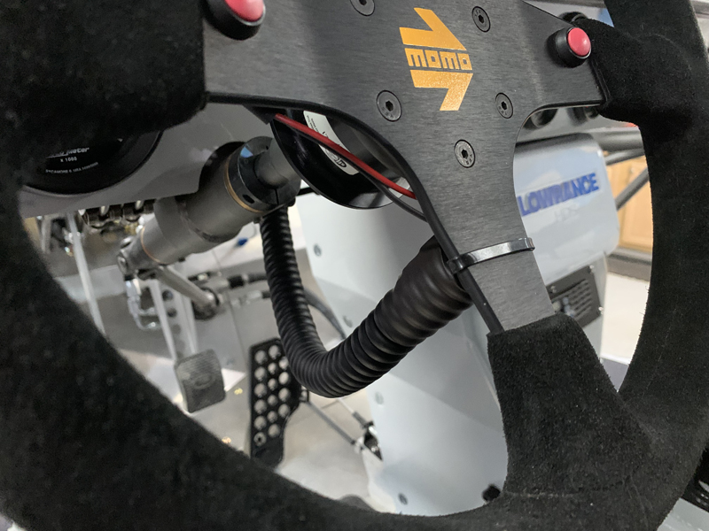
It's "Alive"!
Everything works as expected; all the lights, fans,
pumps, radios, instruments, etc.. We have only the horn buttons
remaining to be connected; we want to be able to remove the
steering wheel so we'll need to be able to disconnect the horn
button wires when we do so. We'll also need to provide for
the rotation of the steering wheel; we'll be using a coiled
cable to allow some "stretch". The coiled cable will be
fitted with a quick disconnect to allow for removal of the
steering wheel.
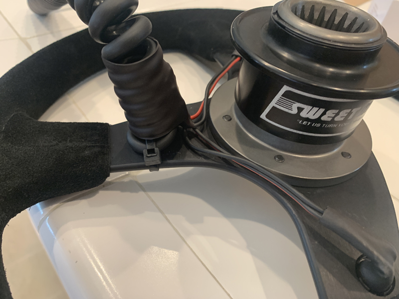
Removable steering wheel cable
We want the steering wheel to be removable from the
car for security reasons - that means that we need to be able to
disconnect the horn button wiring. We used a coiled,
multi-conductor cable to permit free movement of the steering
wheel while in use and installed a male helicopter headset plug
on the free end. The steering wheel has two buttons, wired
together in parallel for the horns. Our original
plan was to separate them to use one for the horns and the other
for a radio transmit button. We later chose to leave them
configured for horns only and mounted a dedicated radio transmit
button for the driver on the dash. We expect that the
co-driver will do most of the radio communications anyway.
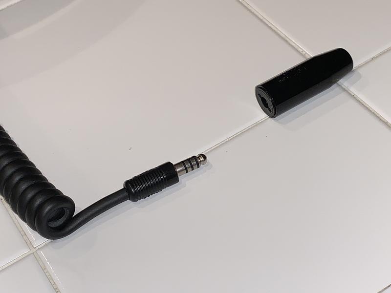
Helicopter headset plug
The helicopter headset connector allows four
different wire connections to be made - we chose these because
our original plan was for the cable to carry both horn and radio
switch signals. Having decided to use the steering
wheel buttons for horns only, we'll now use only two of the four
contacts.
Horn cable installed and functional
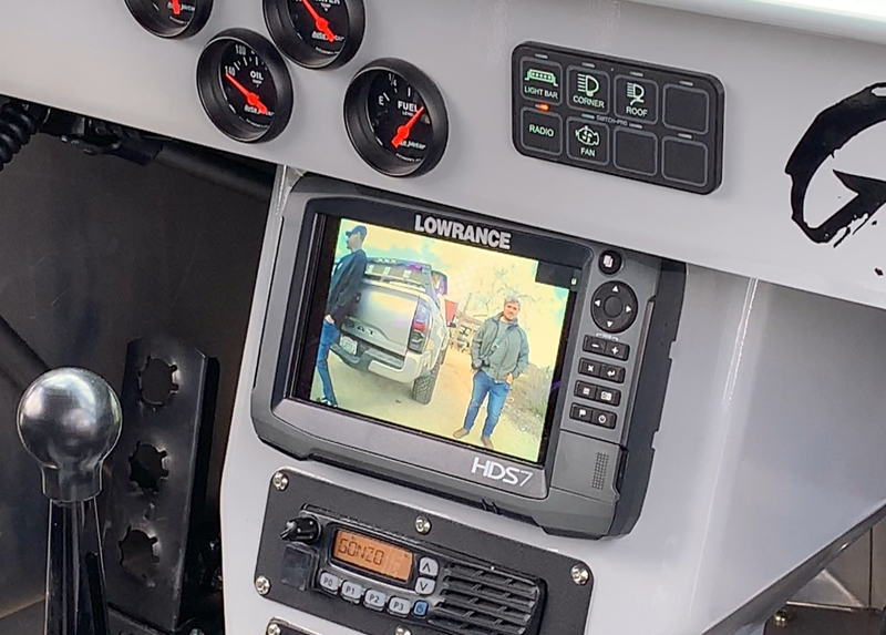
Rear view camera display on GPS
Due to the location of the radiator and spare tire, the
driver has no visibility directly behind the car.
Fortunately, our Lowrance HDS7 can display live video camera
images. We mounted a small wide angle camera on the rear
bumper and can display that view at any time by selecting it
through the GPS touch screen menu. Unfortunately, we can't
configure it to automatically switch to the rear camera view
when "reverse" is selected...
|