|
Now that the driver's seat is mounted, we
can move on to the design and fabrication of shifter and turning
brake mounts. We intend to mount the shifter on top of the
sheet metal "tunnel" and that will require that we fabricate a
support structure that will be mounted to the chassis inside the
tunnel. That support structure will provide a secure
mounting location for the shifter and the reverse lever (we're
not relying on the tunnel itself for support). We chose to
use a Fortin sequential shifter - we liked the look and feel
much better than the usual "Hargett" 2-lever shifter. Our
choice complicates the installation a bit; we'll need to
fabricate and mount a reverse lever in addition to reversing the
direction of shifter operation (the Weddle S5 transaxle we plan
to use requires a "push" from the shifter to "up-shift" and the
Fortin shifter "pulls" in the up-shift direction.....).
We'll solve both problems with the shifter support assembly -
we'll add a lever for reverse and a "bell-crank" to reverse the
shift direction.
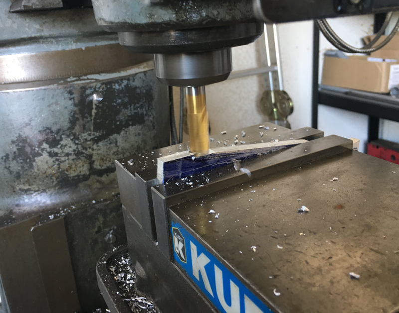
Milling the shift direction changing "bell
crank" to shape
Bell crank bearing ready to be riveted in
place
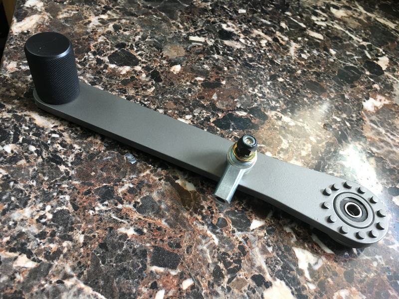
We opted to use a commercially available bell crank bearing
(aircraft part) for longevity, freedom of movement and minimum
slop - we fabricated the remainder. We'll rivet the
bearing to the bell crank arm - all the holes will be filled
with rivets. The bell crank converts a shifter "pull" to a
"push" in order to have correct shifter operation (shift lever
knob rearward for up-shifts and forward for down-shifts).
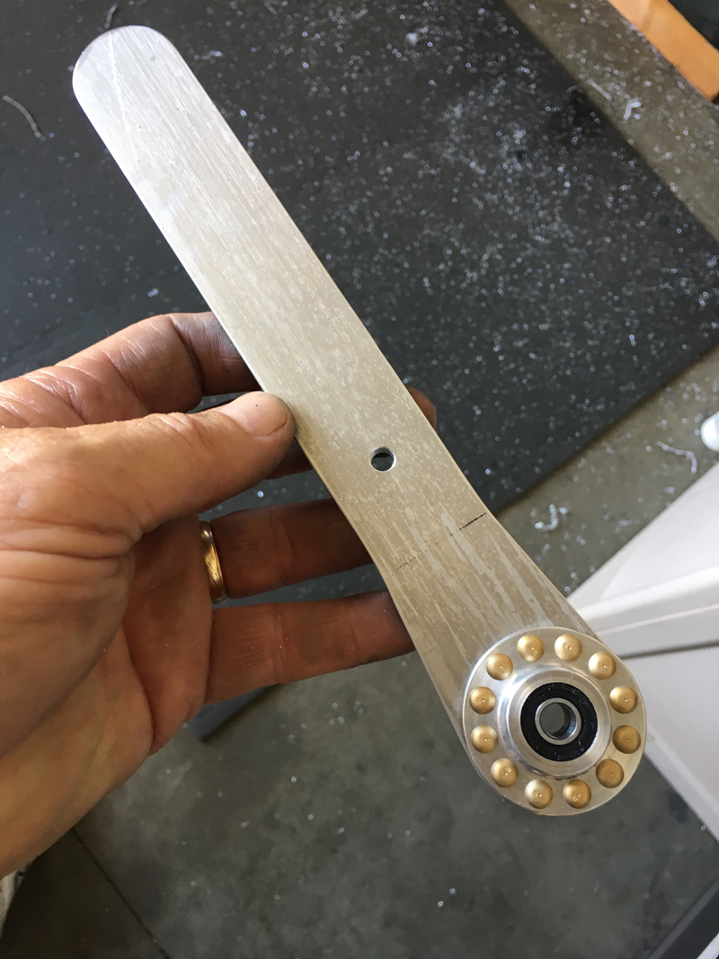
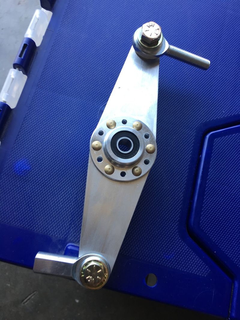
Reverse Lever Fabrication
We fabricated the reverse lever from 2024 aluminum and again
used a bell-crank bearing for smooth operation. We're
fortunate to have the proper riveting tools to make a secure
connection!
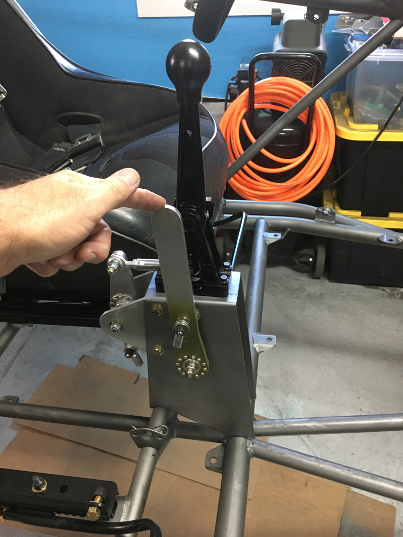
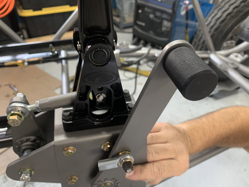
Shifter support structure with shifter,
reverse lever and bell-crank
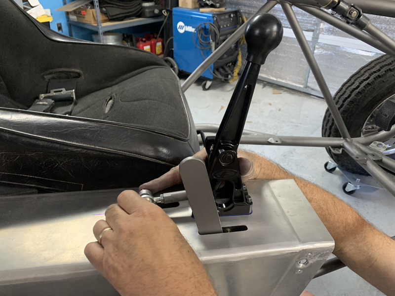
Here, we're fitting the shifter support assembly to the chassis.
We need the assembly to nestle tightly up against the sheet
metal tunnel when everything is mounted; rather than weld the
support structure to the chassis, we chose to weld tabs and bolt
the support in place. That made it easy to get a perfect
fit.
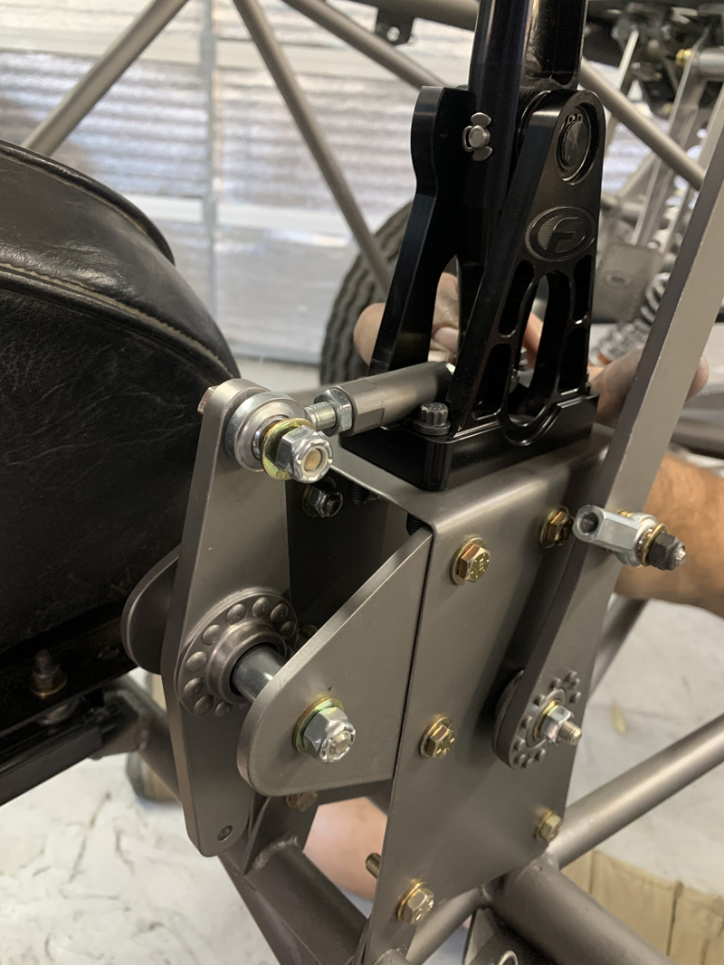
Shifter support assembly installed
Here you can see how the bell crank converts an up-shift
"pull" on the shift knob to a "push" at the shift cable
attachment point. The reverse lever is configured to
require a pull on the handle to select reverse. We'll need
to build a support structure for the "push-pull" cables; they
may be part of the turning brake mount - we need to be careful
to leave room for them once the turning brake assembly is
mounted and it'll probably end up near where the cables will
need to be mounted. This support assembly will be housed
inside the sheet metal "tunnel" and will not be visible except
for the shifter itself, the reverse lever and a small amount of
the upper bell crank and the push rod.
Sheet metal tunnel installed
We've done an initial trim of the tunnel for the reverse lever
and the bell-crank; we'll refine the fit once we determine
exactly how much "throw" we need to get (we think the shifter
throw is sufficient now). Once everything is finalized,
we'll make a cover for the bell-crank and push rod - just to
keep things from jamming it up. We'll be adding a small
"knob" to the reverse lever; it'll give us a more convenient
grip that should eliminate the possibility of scraped
knuckles.....
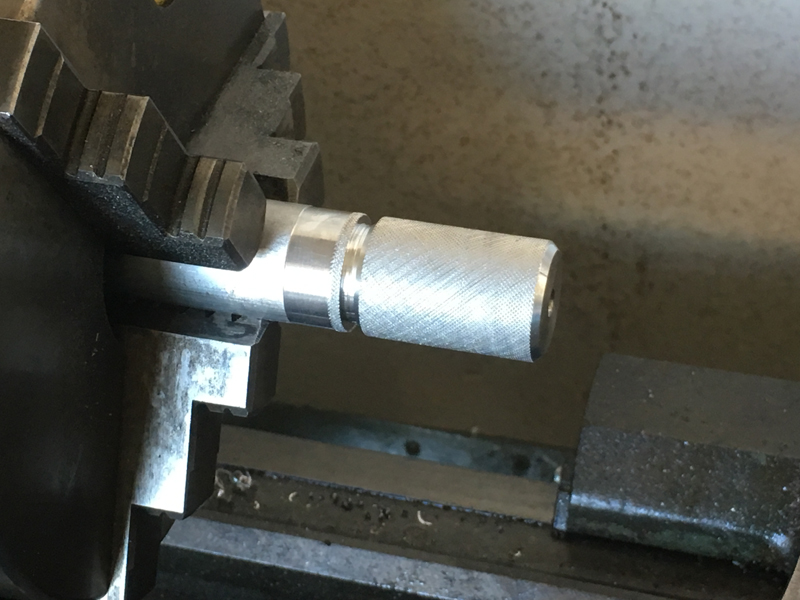
Fabricating the reverse lever knob
Knob painted and installed on reverse lever
Hopefully, the knob will save us a few
"busted knuckles" down the road.....
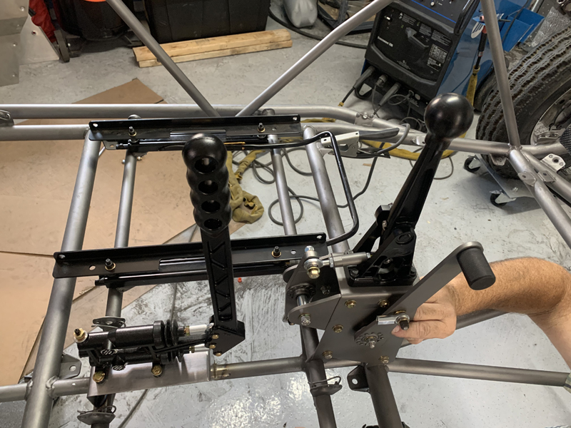
Turning brake mounted
We spent a fair amount of time finding the best location for
our turning brake assembly; we wanted it to be easy to
access/operate but didn't want there to be any interference with
the shifter or reverse lever. We settled on this location
after trying several different spots. We've angled the
turning brake lever away from the driver and towards the
co-driver just a little - it gives us a little more space
between the shifter and the turning brake handle and everything
is readily accessible.
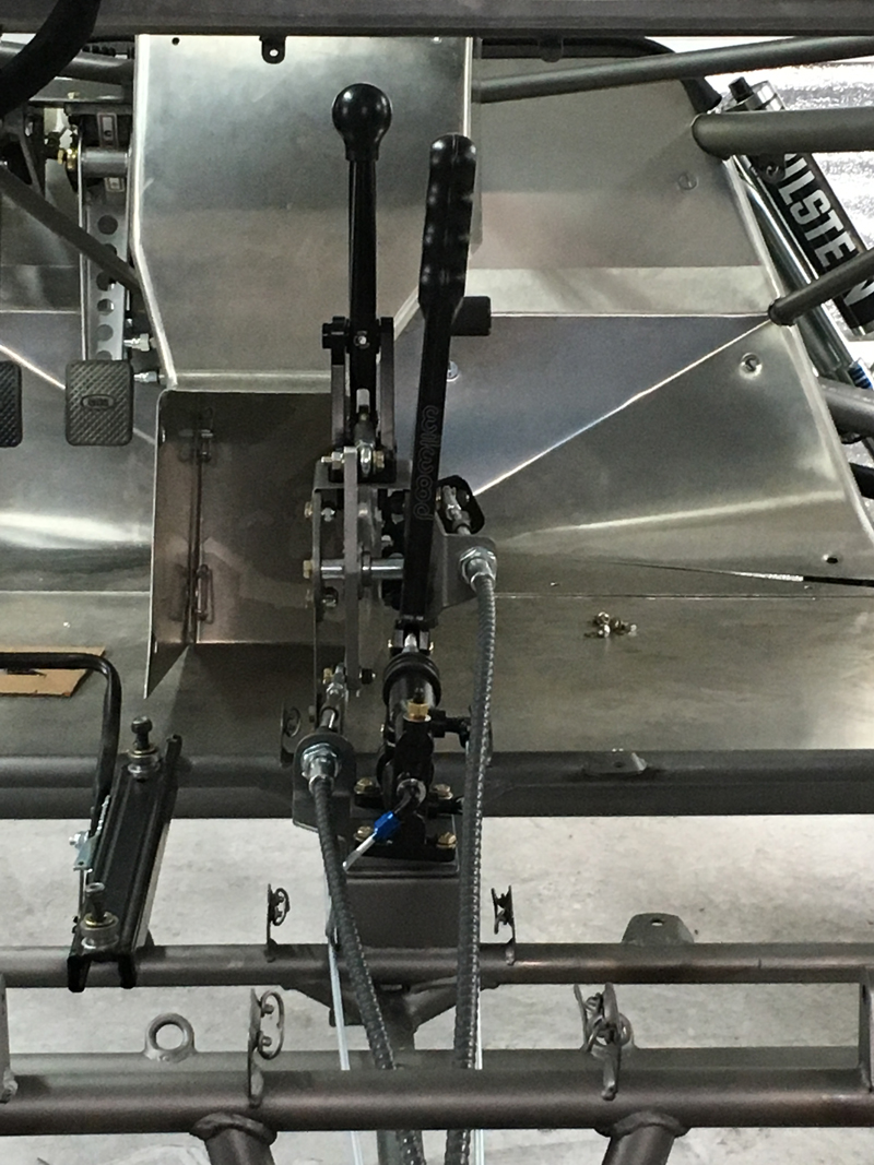
Shifter cable brackets and cables installed
The shifter cables straddle the turning brake assembly; our
decision to angle the turning brake towards the passenger side
required us to offset the reverse selector cable mount a small
amount for clearance, resulting in a small amount of
misalignment of the cable end. Note: the forward portion
of the tunnel is visible in this photo - it is not attached or
in its correct location.....
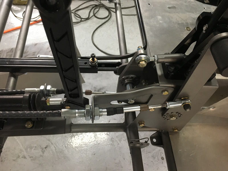
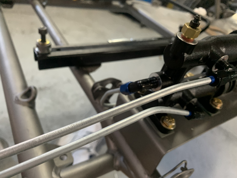
Reverse
lever cable mount and cable
Here, you can see the misalignment of the reverse selector
cable end - it operates smoothly but we may add a spacer under
the rod end to ensure that it continues to do so. Another
option is to open up the mount hole so that we can reposition
the cable inboard enough to eliminate the misalignment.
Forward gears selector cable and mount
installed
This mount is simply "sandwiched" between the turning brake
and its' mount. Easy installation with no modifications
needed. The cables are not yet attached at the transaxle
end or in-between. We'll keep the cables as straight as
possible while still mating to the transaxle at appropriate
angles to minimize any "free-play" in the shifter linkage.
We don't have our transaxle yet; that's a "big ticket" item that
we need to budget for so the aft ends of our cables will remain
unattached until then....
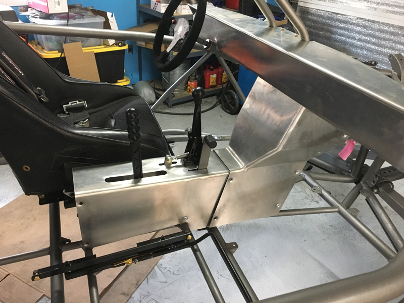
Center tunnel partially installed
Here you can see how everything fits inside the center
tunnel - we're thinking about our options for closing up the
turning brake handle slot in a way that allows free movement but
keeps foreign objects out - a rubber seal or a "brush" type
device are two of the options.
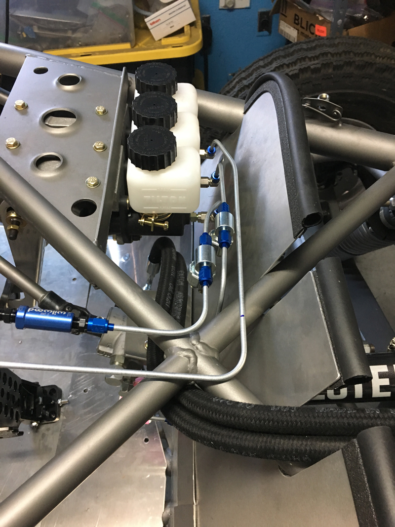
Brake and Clutch master cylinders and lines
Here you can see all three master cylinders and the
beginnings of their respective lines. The topmost cylinder
is for the clutch - no residual valve or light switch needed.
The middle cylinder is for the front brakes - only a brake light
switch needed before going to a firewall "T" then flex lines to
each front brake. The bottom cylinder is for the rear
brakes - a brake light switch and a residual valve before the
line connects to the turning brake assembly. All these
lines will be properly secured once complete. The power
steering lines will not be routed as seen here- they're just
hanging this way to keep them out of the way while we fabricate
the brake and clutch lines.
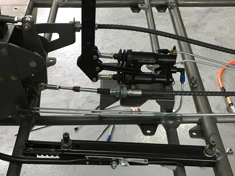
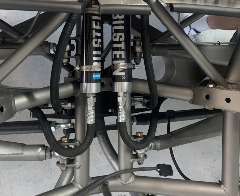
Turning brake lines
The turning brake unit is installed between the brake master
cylinder and the individual rear brakes - a single line in from
the pedal master cylinder and two lines out, one to each rear
brake. We've set up the lines so that we get both brakes
at the same time with pedal pressure, right brake with a pull on
the turning brake handle and left brake with a push.
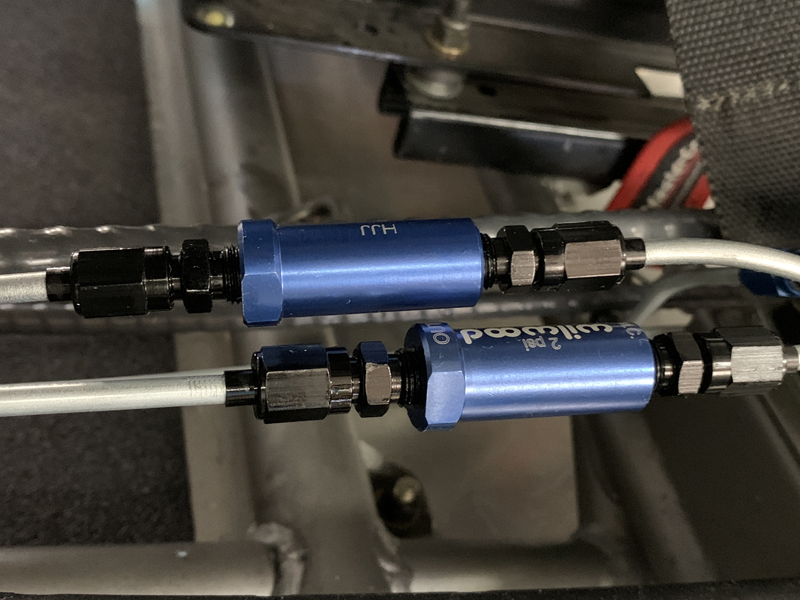
Residual valves installed after the turning
brake unit
We added these residual valves to the lines after the
turning brakes to help "firm them up". We may need to
remove the previously installed single valve near the brake
pedal master cylinder if there's too much "residual pressure"
now...
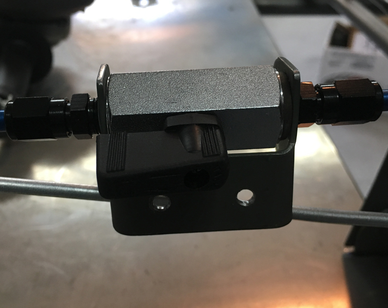
Parking brake "line lock" valve
We wanted to include some sort of parking brake capability,
knowing that we wouldn't use it often but that it would be
useful at some point..... This is a simple stainless steel
ball valve that will allow us to trap brake pressure to the rear
wheels, thereby acting as a parking brake. The valve
mounts to the inside of the tunnel sheet metal within reach of
the driver - the handle is outside the sheet metal while the
body of the valve will be inside.
Steering control valve to rack lines
fabricated and installed
The steering control valve and power rack hydraulic lines
fabricated and installed temporarily. Rather than creating
a new penetration of the foot well area sheet metal, we chose to
route the hoses along structure that already passes through the
area. There is plenty of clearance for them there and this
routing permits us to easily install/remove them without
disturbing the foot well area - it also allows us to remove the
sheet metal without removing the hoses....
|