|
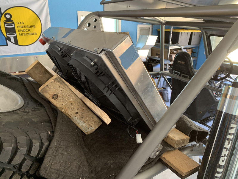
"Mocking up" the radiator installation
We're fortunate to have photos of other Lothringer
pre-runner cars; they all have the radiator mounted in
this location and at this angle. Not wanting to "re-invent
the wheel", we're planning the same.
We'll fabricate a tubular support structure that allows us to
easily remove the radiator and fuel cell for service when
needed. The radiator is mounted at an angle in order
to facilitate the ducting of airflow to it.
Radiator support structure tacked in place
We bent the support hoop using our JD2 bender, fit it
to the radiator and chassis then tacked it in place.
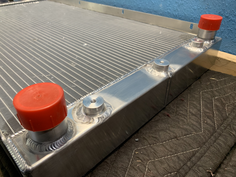
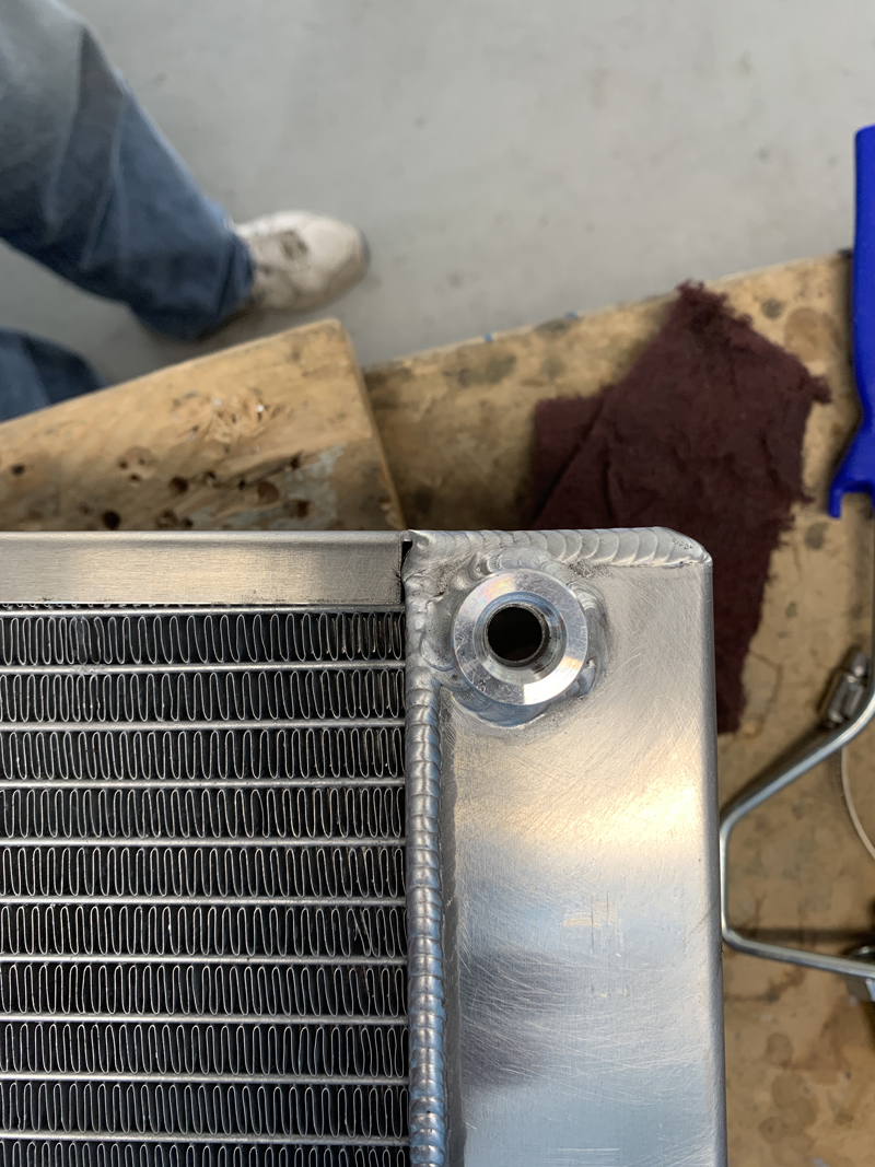
Mount bosses welded to radiator
We fabricated the aluminum "mount bosses" on our
lathe then Trevor welded them in place.
1/4" NPT Boss added to radiator for surge
tank connection
The cooling system has three main components: the radiator,
the surge tank and an overflow tank. The surge tank serves
to eliminate air trapped in the cooling system; this boss allows
any air in the radiator to vent to the surge tank which then
backfills the radiator with coolant. The surge tank vents
to the overflow tank when necessary.
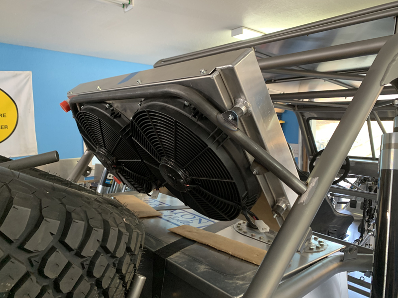
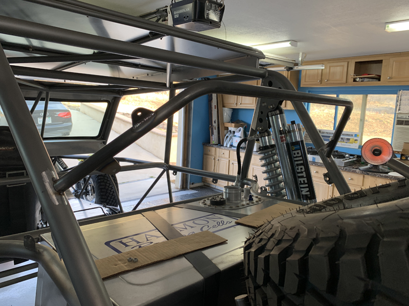
Radiator in place
With the support hoop tacked to the chassis, we
installed the radiator to verify the fit. Four of the six
mount bosses are engaged at this point; we'll fabricate and
install the lower two mount tabs next. Those mount tabs
will require that we add a small chassis tube on each side.
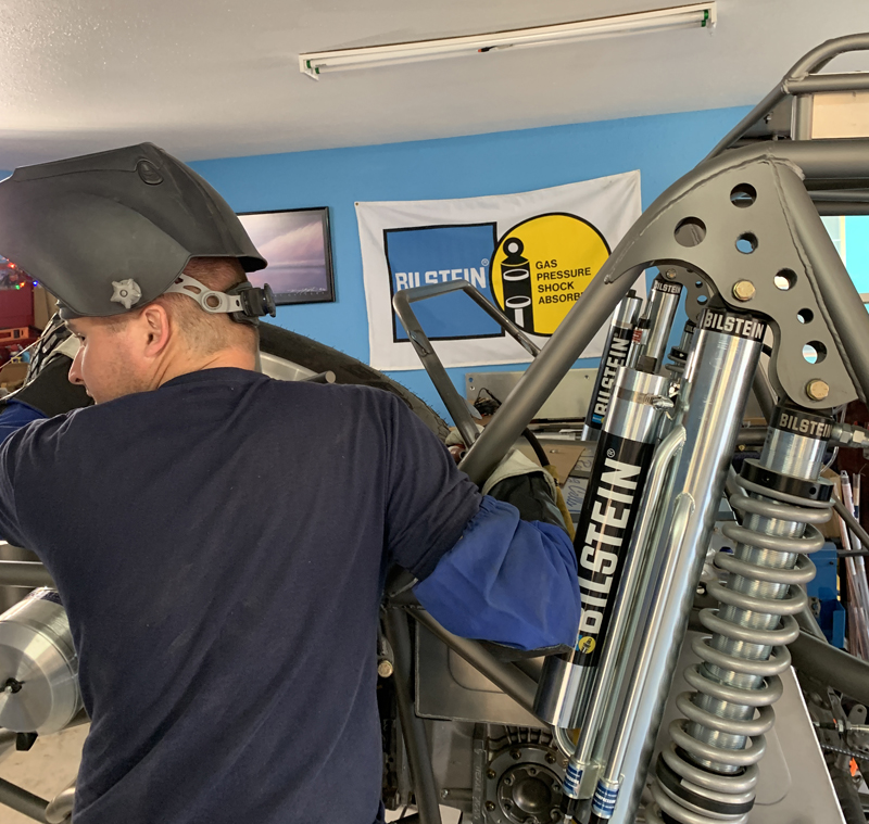
Trevor "final" welding the radiator support
hoop in place
We'll be adding small gussets
to the support hoop/chassis joints, otherwise they'd be "fatigue
crack" problem areas.
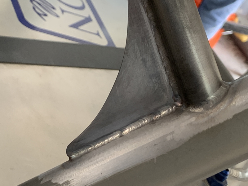
Radiator support hoop gusset installed
This might not be necessary but it's cheap insurance...
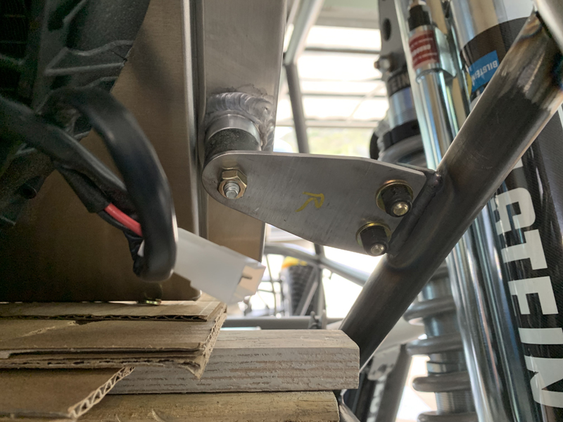
Removable lower radiator support tab
The lower radiator supports must be removable because they
would be in the way when we want to remove the fuel cell.
Once we remove the main tabs, we are left with small mounts that
don't obstruct the fuel cell's removal.
Due to the location of the radiator and the
fact that this car has a windshield, we need to supplement the
natural air flow with a duct to direct air to the radiator from
above the roof line and below the roof rack; there's a
rectangular duct there that provides "ram" air from above the
windshield.
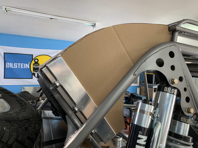
Making patterns for the cooling air duct
mold
The windshield will disrupt the flow of air to the radiator
at high speed - the duct will route air from the passage between
the roof and roof rack to ensure adequate airflow at all speeds.
Here, you see Trevor's patterns for the female mold we'll
construct in order to produce a one-piece carbon fiber duct.
The duct will have rounded corners between the sides and the
upper piece - the "square corners" you see here are only for
creating the basic mold structure... We'll
essentially duplicate the aluminum ducts Kent Lothringer
fabricates for his "turn-key" pre-runners using carbon fiber for
ours.
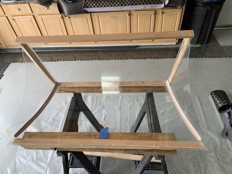
Plexiglass duct mold
Trevor made the duct mold on the car using sheets of
Plexiglas with bondo in the corners for a smooth radius between
the sides and top. Once fitted and glued together, he
removed it from the chassis and added the rounded corners.
The mold was waxed and sprayed with a silicone mold release
agent before the actual layup.
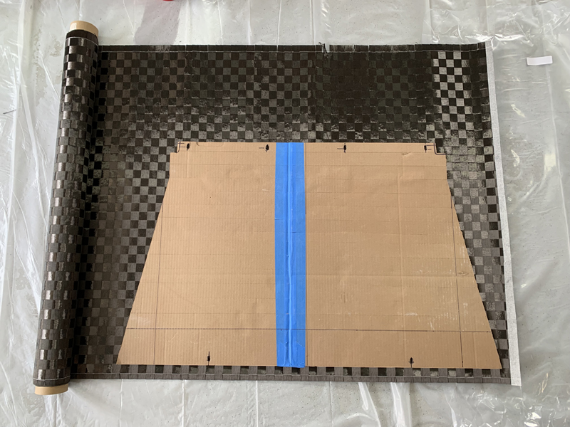
Cutting the carbon fiber cloth
Once the mold was ready, we cut out all the layers of carbon
fabric. Here, we're cutting the first layer (25mm tow) - the one that
will be visible from outside the car. Several reinforcing layers
(2X2 twill) were cut in preparation for the actual molding process so that
the final part will be strong and stiff once the resin cures.
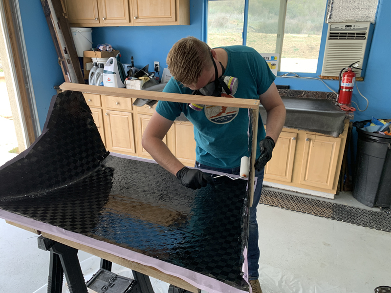
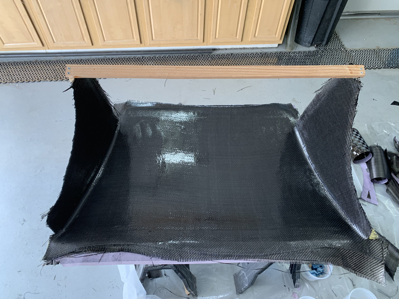
Trevor laying the 25mm "tow" top layer
We have the mold "upside down" to make the layup easier for
us; in this position, the bottom is actually the upper portion of
the finished duct. You may be able to see that the corners
have a generous radius; carbon fiber doesn't do sharp bends
well. In addition to helping ensure that the cloth
conforms to the mold easily, we think that rounded corners have
a more "finished" look... The first layer will be visible from the outside so we chose
a 25mm tow "checker board" pattern. Several 2X2 "twill"
reinforcing layers back the surface layer for strength and
rigidity.
Layup complete
The resin begins to "cure" as soon as it's
catalyzed. The "pot life" (working time) is determined by
the choice of catalyst, size of the batch and temperature - It's hard to pin down precisely
how long you have to work with each batch.
Having all the fabric cut to shape and working quickly is
helpful in ensuring that you can complete the layup with a
minimum of wasted resin. Even with everything ready, it's
difficult (nearly impossible) to work quickly enough to complete
all the layers with a single batch of resin. As the
catalyzed resin starts to "thicken", it will no longer "wet" the
cloth, leading to voids and de-laminations if you continue to
use it. As soon as any thickening is evident, set it
aside, mix a new batch and continue the layup with the newly
mixed resin. Mixing small resin batches as needed is
usually the less wasteful method for large parts...
Once the layup is complete, there is a time
during the cure where it's firm enough, but not too
hard to trim easily with a razor blade. That time is
determined by periodically checking the state of cure by hand -
when it's stiff but not hard, it's time. Trimming with a
razor blade at that point is more precise, easier and cleaner than
waiting for a full cure and using a cut-off wheel (we'll still
have to do some of that)... Now
that we've done the trim, it's just a matter of waiting for a
full cure and removing the part from the mold.
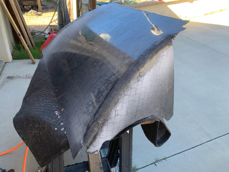
Radiator duct out of the mold
The radiator duct came out of the mold easily
with the exception of the rounded corners - they came out with
the filler we used to create the radius still attached...
Not a huge problem; Trevor chipped it all away without damage to
the actual part. This type of wet layup (no vacuum bags or
resin infusion) produces a fairly smooth surface but leaves
pinholes and small surface voids that must be handled
individually during the "finishing phase". The finishing
phase consists of filling the voids/pinholes, sanding, filling
again, sanding, possibly more filling/sanding and then a final
gloss coat of resin over the smooth part. That's a fair
amount of work; an aluminum duct would probably have been
quicker/easier but we'll have a custom, one-off,
carbon fiber duct that we created...
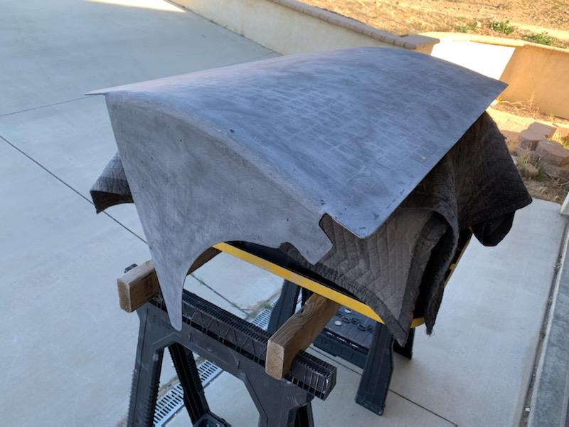
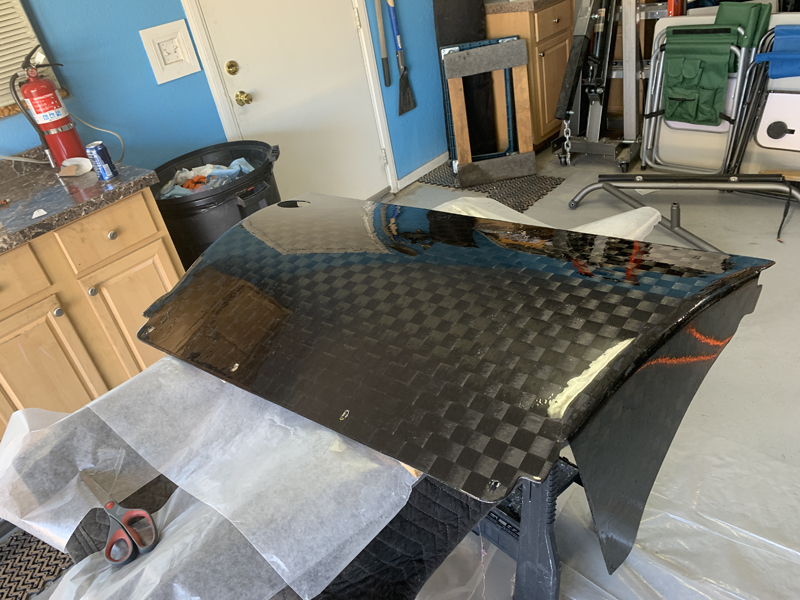
Radiator Duct sanded smooth and flat
Trevor spent hours sanding the duct smooth and flat in
preparation for a final gloss coat. You can still see a
couple of very small "low spots" in this photo but once the
gloss coat is applied, they'll mostly disappear. Prior to
applying the gloss coat, we'll drill the mounting holes and
refine the fit of the duct to the radiator and chassis.
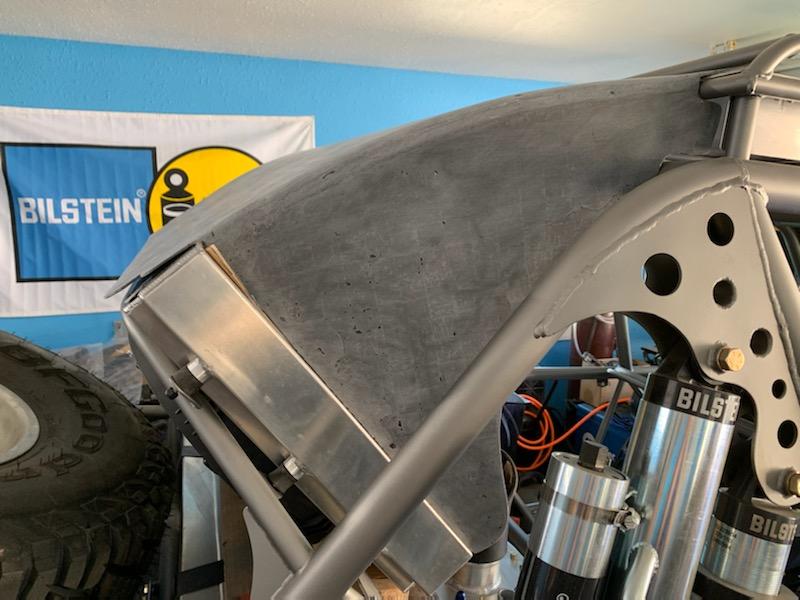
Test-fitting the radiator duct
Prior to final finishing, we wanted to check and "fine tune"
the fit at the radiator and chassis. This is the first
time the final part has been on the car; it looks like a pretty
good fit with only minor adjustments needed. We will not
allow the duct to actually contact the radiator anywhere except
the top face where they bolt to each other - the carbon fiber
would eventually wear a hole in the radiator anywhere they
rubbed against each other...
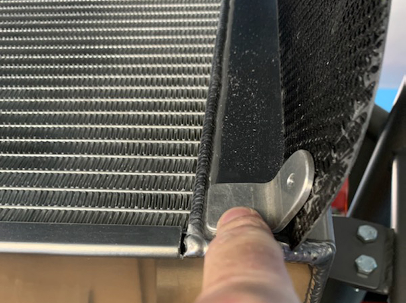
Duct side support tab
We installed a tab on each side of the radiator to support
the duct "wings". These will keep the sides of the duct
from "flapping in the breeze" but more importantly, they'll keep
the duct from rubbing on the radiator and possibly wearing a
hole in it...
First coat of finishing resin applied
This is only the beginning of the finishing process; we'll
need to wet sand smooth and apply at least one more coat of
resin before we get the smooth, glossy look we want. The
25mm "tow" pattern really pops now.
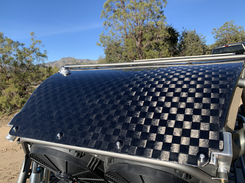
Radiator and duct installed
We think the duct looks spectacular on the car, especially
out in the sun! It fits beautifully and will serve it's
purpose with style...
Trevor created a work of art that'll be functional as well.
|